


j Whenusingasubwooferof 70W(2 Ω),be
suretoconnect thesubwooferto theviolet
andviolet/blackleads ofthis unit.Donot
connectanythingto thegreenand green/
blackleads.
k Notused.
l Subwoofer(4Ω)×2
Notes
! Witha2speaker system,do notconnectany-
thingtothe speakerleadsthat arenotcon-
nectedtospeakers.
! Changetheinitial settingof thisunit.Refer
toSWCONTROL (rearoutput andsubwoofer
setting)onpage 11.
Thesubwooferoutput ofthis unitismonau-
ral.
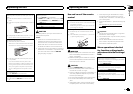
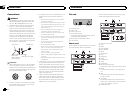
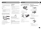
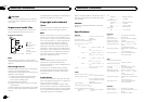
Power amp (sold separately)
Performtheseconnections whenusingthe op-
tionalamplifier.
1
1
3
2
4
55
3
2
6
77
1 Systemremotecontrol
ConnecttoBlue/white cable.
2 Poweramp(sold separately)
3 ConnectwithRCAcables(sold separately)
4 To Rearoutputor subwooferoutput
5 Rearspeakerorsubwoofer
6 To Front output
7 Frontspeaker
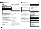
Installation
Important
! Checkallconnections andsystemsbefore
finalinstallation.
! Donotuse unauthorizedpartsas thismay
causemalfunctions.
! Consultyourdealer ifinstallationrequires
drillingofholes orothermodifications tothe
vehicle.
! Donotinstall thisunitwhere:
— itmayinterferewithoperationofthevehicle.
— itmaycauseinjurytoapassengerasaresult
ofasuddenstop.
! Thesemiconductorlaser willbe damagedif
itoverheats.Install thisunitaway fromhot
placessuchas neartheheater outlet.
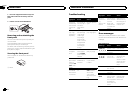
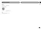
! Optimumperformanceisobtained whenthe
unitisinstalled atanangle oflessthan 60°.
60°
DIN front/rear mount
Thisunitcan beproperlyinstalled usingeither
front-mountorrear-mountinstallation.
Usecommerciallyavailable partswheninstal-
ling.
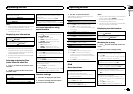
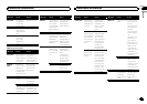
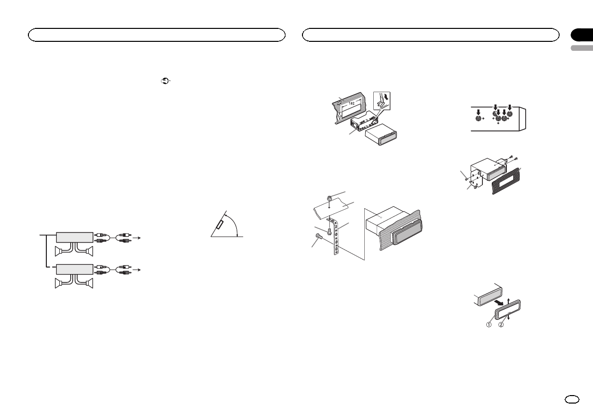
DINFront-mount
1 Insertthemounting sleeveintothe dash-
board.
Forinstallationinshallowspaces, usethesup-
pliedmountingsleeve. Ifthere isenoughspace,
usethemounting sleevethatcame withtheve-
hicle.
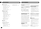
2 Securethemountingsleeve byusinga
screwdrivertobendthe metaltabs(90°) into
place.
1
2
1 Dashboard
2 Mountingsleeve
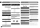
3 Installtheunit asillustrated.
1
2
3
4
5
1 Nut
2 Firewallormetalsupport
3 Metalstrap
4 Screw
5 Screw(M4×8)
# Makesurethattheunitisinstalledsecurelyin
place.Anunstableinstallationmaycauseskipping
orothermalfunctions.
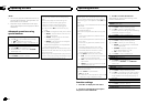
DINRear-mount
1 Determinetheappropriateposition
wheretheholeson thebracketand theside
oftheunit match.
2 Tightentwoscrewson eachside.
1
2
3
1 Screw
2 Mountingbracket
3 Dashboardorconsole
! Useeithertruss(5mm×8mm)orflushsur-
face(5mm×9mm)screws,dependingon
thebracketscrewholes.
Removingthe unit
1 Removethetrim ring.
1 Trimring
2 Notchedtab
! Releasingthefrontpanelallowseasierac-
cesstothetrimring.
! Whenreattachingthetrimring,pointthe
sidewiththenotchedtabdown.
English
Installation
03
13
Section
Installation
En