


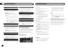
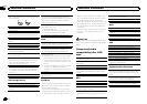
This unit
1 2
34756
8
a
9
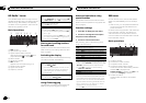
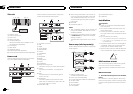
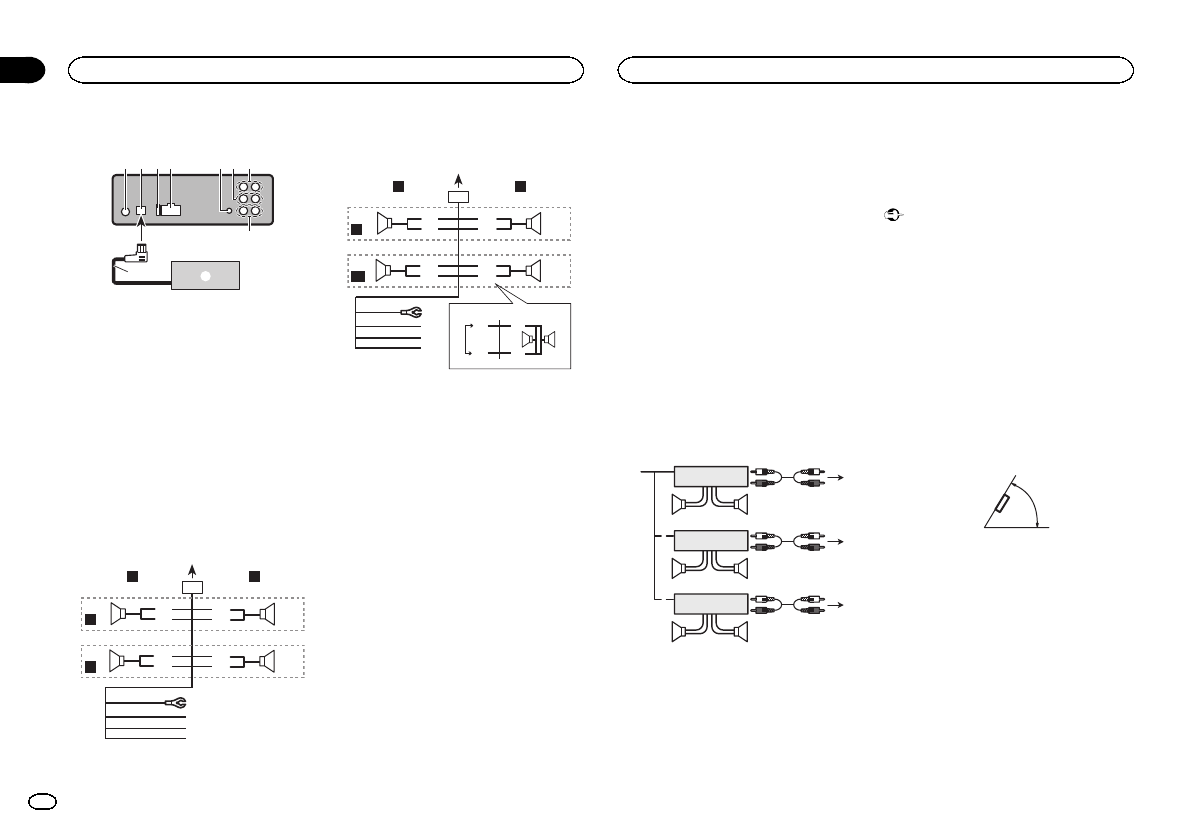
1 Antennainput
2 IP-BUSinput(blue)
3 Fuse(10A)
4 Powercordinput
5 Wiredremoteinput
Hard-wiredremotecontrol adaptorcanbe
connected(soldseparately).
6 Frontoutput
7 Rearoutput
8 Subwooferoutput
9 IP-BUScable(soldseparately)
a PioneerIP-BUSaccessories(soldseparately)
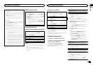
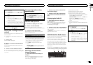
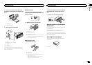
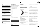
Power cord
Performtheseconnections whennotconnect-
ingarear speakerleadto asubwoofer.
1
8
9
c
d
6
32
4
5
7
a
b
e
f
h
g
LR
F
R
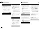
Performtheseconnections whenusinga sub-
wooferwithout theoptionalamplifier.
1
8
9
c
d
6
32
4
7
a
b
a
b
e
f
h
g
LR
F
SW
i
j
d
c
k l
1 To powercordinput
2 Left
3 Right
4 Frontspeaker
5 Rearspeaker
6 White
7 White/black
8 Gray
9 Gray/black
a Green
b Green/black
c Violet
d Violet/black
e Black(chassisground)
Connecttoa clean,paint-freemetal location.
f Yellow
Connecttothe constant12V supplytermi-
nal.
g Red
Connecttoterminal controlledbyignition
switch(12V DC).
h Blue/white
Connecttosystem controlterminalof the
powerampor auto-antennarelaycontrol ter-
minal(max.300 mA12V DC).
i Subwoofer(4Ω)
j Whenusingasubwooferof 70W(2 Ω),be
suretoconnect thesubwooferto theviolet
andviolet/blackleads ofthis unit.Donot
connectanythingto thegreenand green/
blackleads.
k Notused.
l Subwoofer(4Ω)×2
Notes
! Witha2speaker system,do notconnectany-
thingtothe speakerleadsthat arenotcon-
nectedtospeakers.
! Changetheinitial settingof thisunit.Refer
toS/Wcontrol(rearoutput andsubwoofer
setting)onpage 11.
Thesubwooferoutput ofthis unitismonau-
ral.
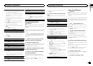
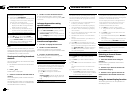
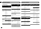
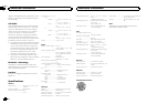
Power amp (sold separately)
Performtheseconnections whenusingthe op-
tionalamplifier.
1
1
3
2
4
55
3
2
6
77
1
3
2
8
99
1 Systemremotecontrol
ConnecttoBlue/white cable.
2 Poweramp(sold separately)
3 ConnectwithRCAcables(sold separately)
4 To Rearoutput
5 Rearspeaker
6 To Front output
7 Frontspeaker
8 To subwooferoutput
9 Subwoofer
Installation
Important
! Checkallconnections andsystemsbefore
finalinstallation.
! Donotuse unauthorizedpartsas thismay
causemalfunctions.
! Consultyourdealer ifinstallationrequires
drillingofholes orothermodifications tothe
vehicle.
! Donotinstall thisunitwhere:
— itmayinterferewithoperationofthevehicle.
— itmaycauseinjurytoapassengerasaresult
ofasuddenstop.
! Thesemiconductorlaser willbe damagedif
itoverheats.Install thisunitaway fromhot
placessuchas neartheheater outlet.
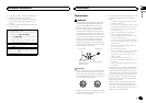
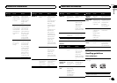
! Optimumperformanceisobtained whenthe
unitisinstalled atanangle oflessthan 60°.
60°
DIN front/rear mount
Thisunitcan beproperlyinstalled usingeither
front-mountorrear-mountinstallation.
Usecommerciallyavailable partswheninstal-
ling.
DINFront-mount
1 Insertthemounting sleeveintothe dash-
board.
Forinstallationinshallowspaces, usethesup-
pliedmountingsleeve. Ifthere isenoughspace,
usethemounting sleevethatcame withtheve-
hicle.
Installation
04
22
Section
Installation
En