


Connecting your equipment
03
36
En
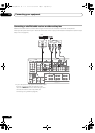
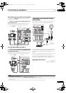
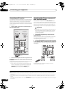
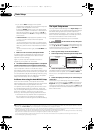
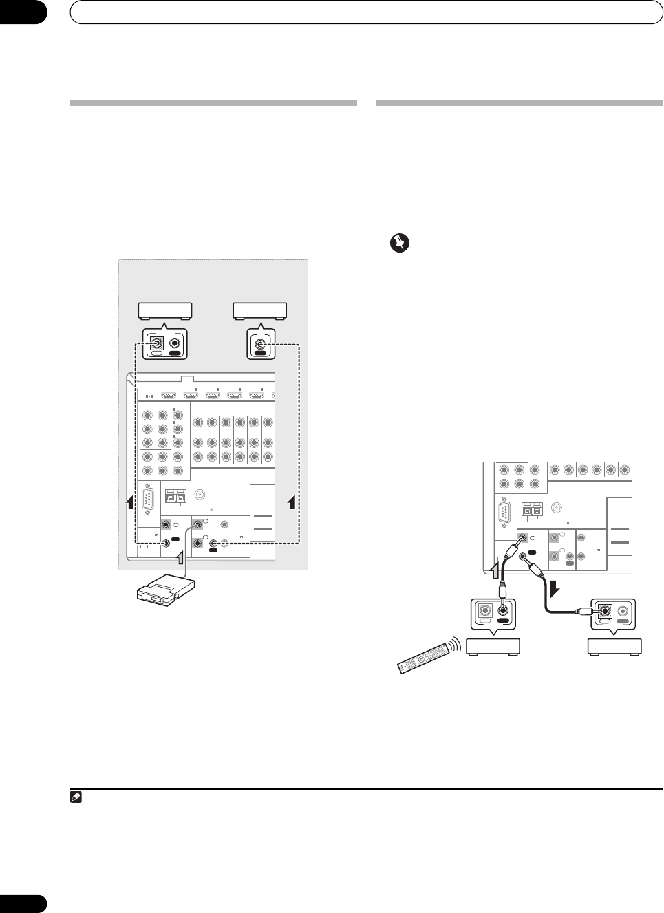
Connecting an IR receiver
If you keep your stereo components in a closed cabinet or
shelving unit, or you wish to use the sub zone remote
control in another zone, you can use an optional IR
receiver (such as a Niles or Xantech unit) to control your
system instead of the remote sensor on the front panel of
this receiver.
1
1 Connect the IR receiver sensor to the
IR IN
jack on
the rear of this receiver.
2 Connect the
IR IN
jack of another component to the
IR OUT
jack on the rear of this receiver to link it to the
IR receiver.
Please see the manual supplied with your IR receiver for
the type of cable necessary for the connection.
• If you want to link a Pioneer component to the IR
receiver, see Operating other Pioneer components
with this unit’s sensor below to connect to the
CONTROL jacks instead of the IR OUT jack.
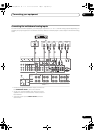
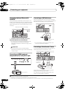
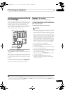
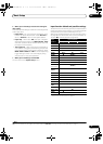
Operating other Pioneer components
with this unit’s sensor
Many Pioneer components have SR CONTROL jacks
which can be used to link components together so that
you can use just the remote sensor of one component.
When you use a remote contr ol, the control signal is
passed along the chain to the appropriate component.
2
Important
• Note that if you use this feature, make sure that you
also have at least one set of analog audio, video or
HDMI jacks connected to another component for
grounding purposes.
1 Decide which component you want to use the
remote sensor of.
When you want to control any component in the chain,
this is the remote sensor at which you’ll point the
corresponding remote control.
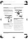
2 Connect the
CONTROL OUT
jack of that component
to the
CONTROL IN
jack of another Pioneer component.
Use a cable with a mono mini-plug on each end for the
connection.
Continue the chain in the same way for as many
components as you have.
Note
1• Remote operation may not be possible if direct light from a strong fluorescent lamp is shining on the IR receiver remote sensor window.
• Note that other manufacturers may not use the IR terminology. Refer to the manual that came with your component to check for IR
compatibility.
• If using two remote controls (at the same time), the IR receiver’s remote sensor takes priority over the remote sensor on the front panel.
RS-232C
HDMI
ASSIGNABLE
COMPONENT VIDEO
ASSIGNABLE
MONITOR OUT
ZONE 2 OUT
IN
Y
ANTENNA
FM UNBAL 75 AM LOOP
ZONE2
OUT
ZONE3
OUT
DVD
IN
TV/SAT
IN
VIDEO
IN
DVR/
OUT
P
R
P
B
1
INBD
IN
1
IN
2
IN
3
1 4
(
DVD
)
IN
2
(
DVR/BDR
)
IN
3
(
VIDEO
)
CONTROL
EXTENSION
IR 12 V
TRIGGER
IN
IN
IN
OUT
OUT
1
2
1
2
(OUTPUT
12 V
TOTAL
150 mA MAX)
IN
4
(
OUTPUT 5 V
150 mA MAX
)
SPEAKERS
Class 2 Wiring
SEE INSTRUCTIO
MANUAL
SELECTABLE
VOIR LE MODE
D'EMPLOI
SELECTABLE
IN
IR
IN OUT
CONTROL
IR receiver
Closet or shelving unit
Non-Pioneer
component
Pioneer
component
2 • If you want to control all your components using this receiver’s remote control, see Setting the remote to control other components on
page 68.
• If you have connected a remote control to the CONTROL IN jack (using a mini-plug cable), you won’t be able to control this unit using the
remote sensor.
CONTROL
IN
OUT
RS-232C
MONITOR
OUT
ZONE 2 OUT
Y
ANTENNA
FM UNBAL 75 AM LOOP
P
R
P
B
EXTENSION
IR 12 V
TRIGGER
IN
IN
OUT
1
2
1
2
(OUTPUT
12 V
TOTAL
150 mA MAX)
(
OUTPUT 5 V
150 mA MAX
)
SPEAKERS
Class 2 Wiring
SEE INSTRUCTI
O
MANUAL
SELECTABLE
VOIR LE MODE
D'EMPLOI
SELECTABLE
CONTROL
IN OUT
IN OUT
CONTROL
SC-1525_UXJCB.book 36 ページ 2010年4月20日 火曜日 午後7時32分