


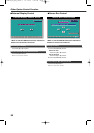
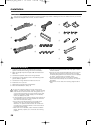

Installation
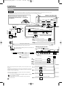
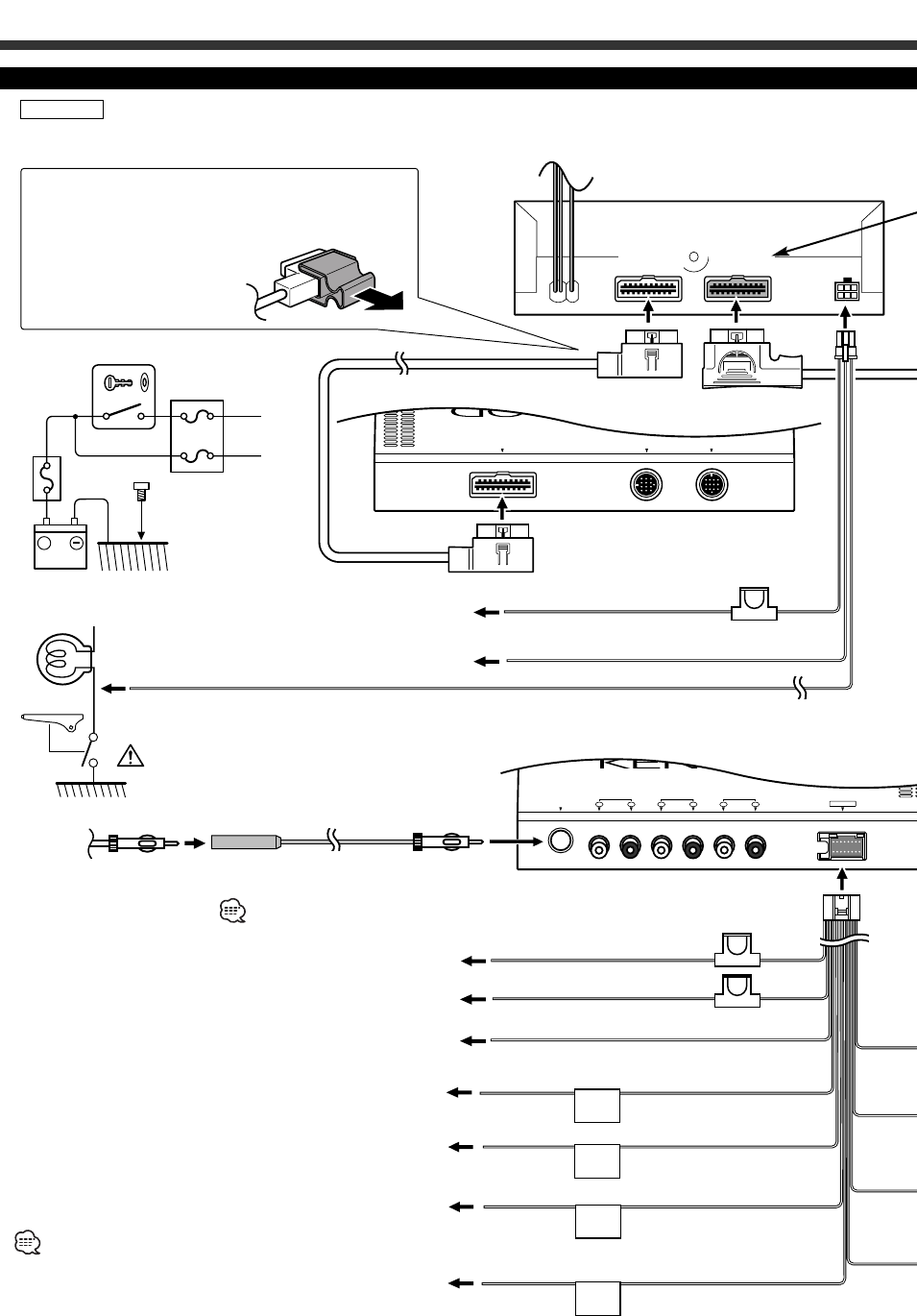
Connection
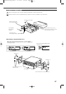
FRONT
REAR
L R
FRONT
L R
NON-FAD
L R
FM/AM
ANTENNA
POWER
TO 5L I/F TO NAV. I/F TO MONITOR UNIT
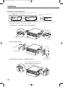
L R
FRONT REAR
L R
NON-FAD
L R
FM/AM
ANTENNA
POWER
TO 5L I/F TO NAV. I/F TO MONITOR UNIT
( 3A )
( 10A )
A
B
C
P.
CONT
ANT
CONT
EXT.
CONT
( 5A )
B
C
+
A
B
C
TEL
MUTE
To parking brake detection switch harness of car
For the sake of safety, be sure to connect the
parking sensor.
Antenna Cord (Accessory D)
Route wiring away
from power circuitry
to avoid noise.
FM/AM
antenna input
Accessory C
Receiver Unit (Front side)
Receiver Unit (Rear side)
Monitor Unit (Rear side)
Accessory A
TEL mute wire (Brown)
Connect to the terminal that is grounded when either the telephone
rings or during conversation.
To connect the KENWOOD navigation system, consult
your navigation manual.
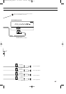
Ignition wire (Red)
Battery wire (Yellow)
Ground wire (Black) - (To car chassis)
When using the optional power amplifier, connect to its power control
terminal.
Depending on what antenna you are using, connect either to the control
terminal of the motor antenna, or to the power terminal for the booster
amplifier of the film-type antenna.
Power control wire (Blue/White)
Motor antenna control wire (Blue)
External amplifier control wire (Pink / Black)
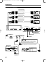
If you connect the ignition wire (red) and the battery wire (yellow) to the car chassis (ground), you may cause a short circuit, that in
turn may start a fire. Always connect those wires to the power source running through the fuse box.
2WARNING
Battery wire (Yellow)
Ground wire (Black) - (To car chassis)
To "EXT.AMP.CONT." terminal of the amplifier having the external
amp control function.
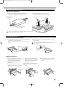
When detaching the connection cable, use
the accessory tool (Accessory-L) as shown in
the diagram.
Accessory B
40
Ignition key switch
Car fuse box
(Main fuse)
ACC
Battery
Parking sensor cable (Green)
(Black)
(White)
KVT-M700(K)_Eng_ver01.1 01.12.20 7:20 PM Page 40