


10
11
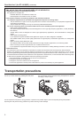
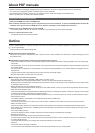
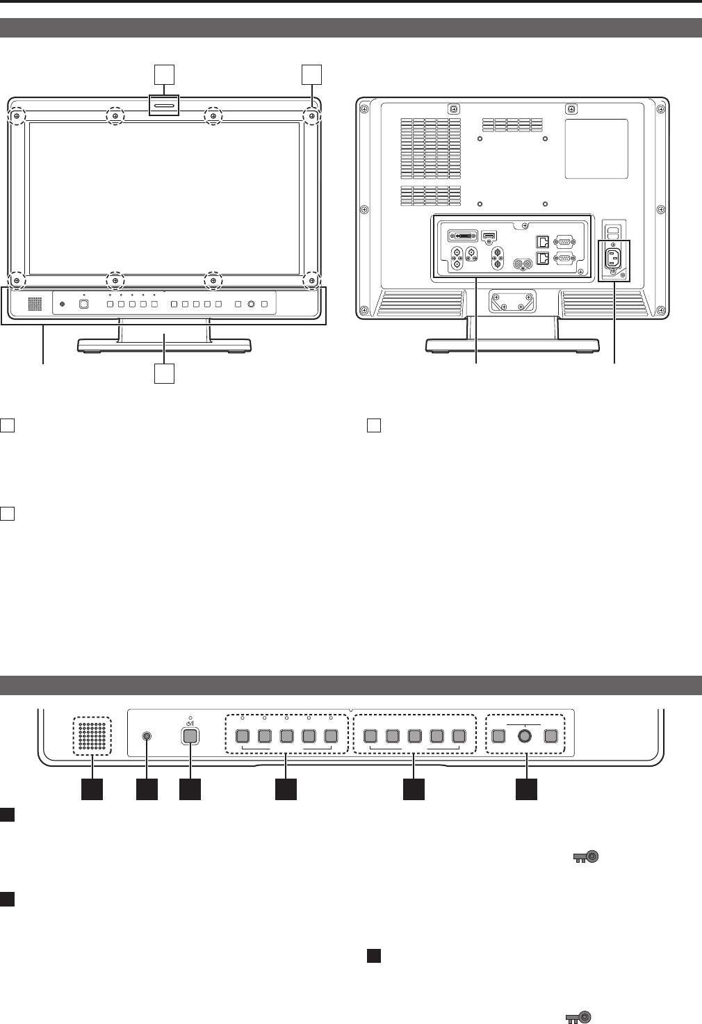
Controls and Their Functions
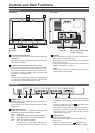
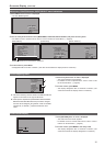
Video monitor
Front panel Rear panel
1
3
2
Rear panel
(→page 12)
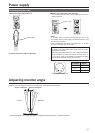
Power supply
(you can switch between AC
and DC (→page 13))
Front panel
(This page)
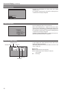
1
Tally Lamps (Red and Green)
Can be lit by a control signal (red tally and green tally) from
a GPI/camera.
If the red tally and green tally light at the same time, the tally
color will become amber.
2
Protective panel mounting screw holes (8 holes)
Eight screw holes have been provided to enable attachment
of a permanent protection panel. The screws for the protec-
tive panel are installed in the mounting screw holes at time
of shipment. To attach a protective panel, first remove the
screws before securing the panel.
<Note>
The LCD panel is shipped covered with a packaging material
to protect it from damage during unpacking and transporta-
tion. Remove the panel before using the monitor.
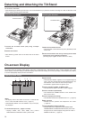
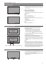
3
Tilt Stand
The tilt stand allows you tilt the unit approx. 10 degrees for-
ward or approx. 15 degrees backward.
When tilting the unit, firmly hold the bottom of the stand and
move the top of the unit.
If you want to remove the tilt stand, refer to “Detaching and
Attaching the Tilt Stand” (→page14).
<Note>
• When tilting the monitor, be careful not to trap your hand
between the monitor and stand.
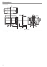
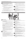
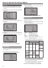
Front panel
HEADPHONES VIDEO SDI 1
INPUT SELECT
SDI 2 HDMI DVI-I 1 2
FUNCTION
3
VOLUMEPICTURE
4 5 MENU RETURN
5 6 1 2 3 4
1
POWER switch
Switches the power supply ON/OFF. When the power is ON,
the LED (green) lights.
To turn the power off, press and hold the switch for at least
three seconds.
2
INPUT SELECT button
Selects the signal input line. The green LED light above the
pressed button indicates the selected input signal.
VIDEO : Video input
SDI1 : Serial digital interface input (HD/SD compatible)
SDI2 : Serial digital interface input (HD/SD compatible)
HDMI : HDMI input (HDCP compatible)
DVI-I : DVI-I input (HDCP compatible)
• Selects one of four input signals: digital video or
PC signal, analog video or PC signal. (→page 38)
• The input line when the power supply is switched ON is the
one that was selected the last time the power was switched
OFF.
• When the control lock is on, the
mark appears and
input lines cannot be changed. (→page 41)
• When INT-SG (internal chart for adjustment “Color Bar +
Grayscale”) is selected, all LEDs above the INPUT SE-
LECT button are off. Use the “INPUT SELECT” menu to
select INT-SG. (→page 18)
3
FUNCTION button
FUNCTION1 to FUNCTION5:
Press to use function assigned to the FUNCTION button
with the menu.
• When the control lock is on, the
mark appears to
indicate that FUNCTION operation is disabled. (→page 41)