


12
Controls and Their Functions (continued)
13
4
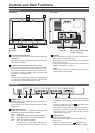
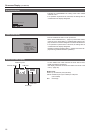
MENU button, rotary knobs (with push-on switch (PIC-
TURE)) and RETURN/VOLUME button (→page 15)
Use these buttons to display menus, select and adjust set-
tings and perform menu selections.
MENU: Press to display the TOP MENU (main menu,
FUNCTION menu and INPUT SELECT menu) or to
exit from a menu.
Rotary knob:
Turn the knob clockwise or counterclockwise to move
the cursor up or down or to change set values.
Press the knob to start changing set values, to con-
firm them and to open submenus.
RETURN:
Press to return to the previous menu or cancel to re-
cover a previously set value.
When no menu is open, press the rotary knob or RETURN
button to open a menu other than the TOP MENU.
PICTURE:
When no menu is displayed, press the rotary knob to
open the picture adjusting menu. (→page 15)
VOLUME:
When no menu is displayed, press the RETURN but-
ton to open the audio volume bar meter. (→page 15)
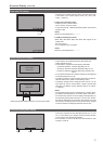
5
Speaker (monaural)
Enables monitoring of analog AUDIO, SDI and HDMI signal
inputs.
• Connecting headphones to the HEADPHONES output jack
turns off the speaker.
6
HEADPHONES output jack (M3 stereo mini jack)
Allows you to connect headphones to monitor analog audio,
SDI and HDMI signal input.
• The volume and sound quality differ depending on the
headphones.
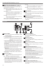
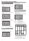
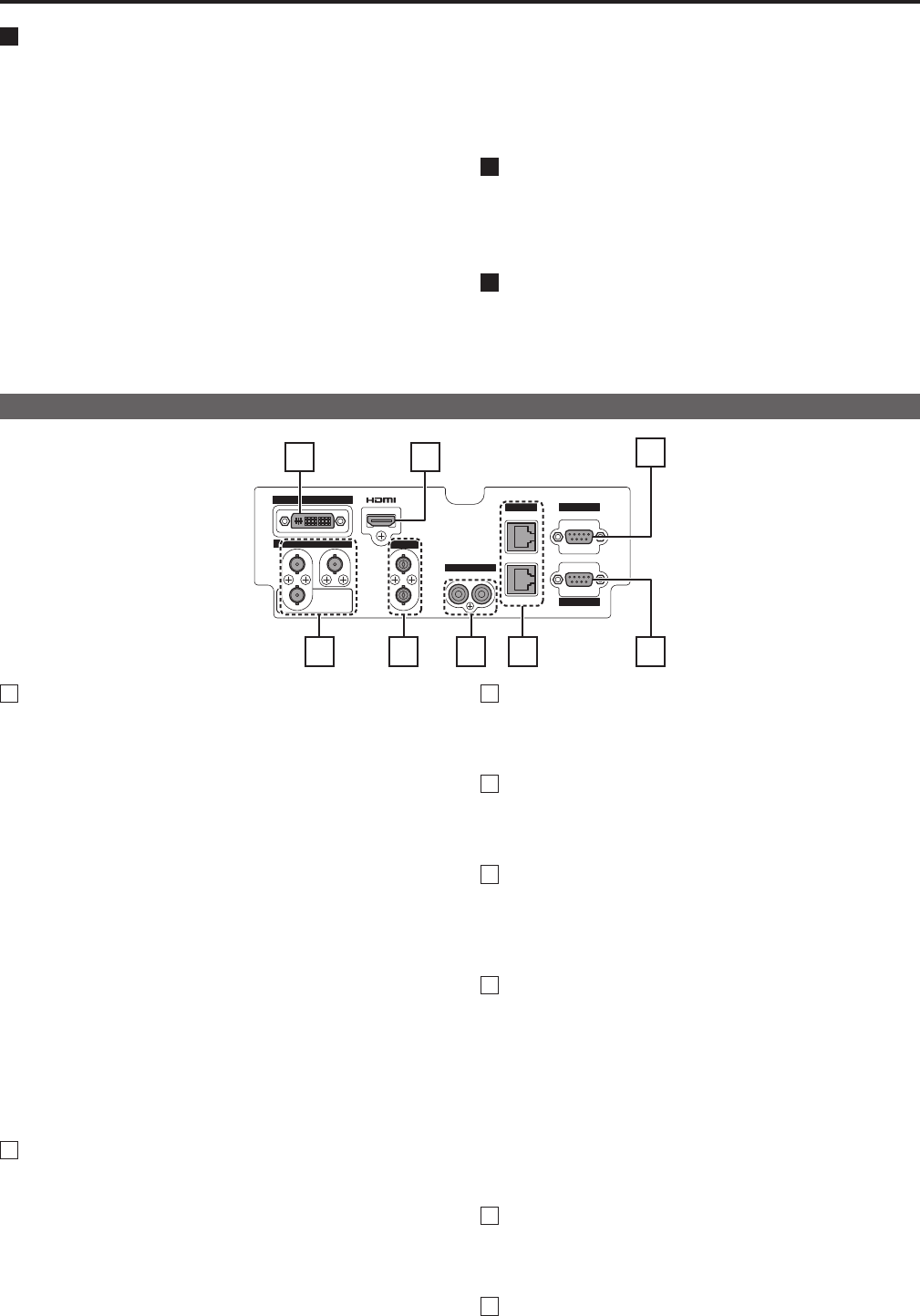
Rear panel
IN
1 2
IN
IN
R L
IN
OUT
OUT
1 2 6 85
3
4
7
1
SDI terminal (BNC)
IN1: This is the SDI input terminal (compatible with HD/SD
automatic switching).
IN2: This is the SDI input terminal (compatible with HD/SD
automatic switching).
SWITCHED OUT: This is the active through-out terminal for
the SDI input signal being displayed on
the screen.
• Active SDI through-out is only output when [SDI1] or [SDI2]
is selected using [INPUT SELECT]. It is not output when
something other than SDI is selected. Embedded audio is
also supported.
When this output is used to daisy-chain
*
1
multiple monitors,
the quality of the original signal, cable length, the number
of connected devices and other factors all come into play to
deteriorate picture quality and introduce noise.
*
1
Daisy-chain:
Refers to connecting the through-out signal from a device
to the input of a second, third or more devices in a linear
series, thus using a single signal in multiple devices.
• Use a 5C-FB or equivalent cable to make connections to
an SDI terminal.
2
VIDEO terminal (BNC)
*
2
*
3
IN: This is the VIDEO signal (composite signal) input ter-
minal.
OUT: This is the input signal through-out terminal.
*
2
Unless a cable is connected to the OUT terminal, the VID-
EO IN terminal is automatically terminated at 75 Ω. Con-
necting a cable releases this termination.
*
3
Since a connection to the through-out terminal releases
the 75 Ω termination of the unit, the level of the VIDEO
signal input to the unit may become too large depending
on the connected device.
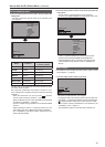
3
DVI-I terminal (single link)
This is the DVI-signal input terminal.
• Use double shielded cable for making connections to a
DVI-I terminal.
4
HDMI terminal (Type A)
This is the HDMI input terminal.
• Use double-shielded cable for making connections to an
HDMI terminal.
5
AUDIO input terminal (pin jack)
This is the common audio input terminal for all video input
terminals.
• Use shielded cable for making connections to an AUDIO
input terminal.
6
RS-485 input/output terminal (RJ-45)
External control is possible by using an RS-485 signal.
• Use shielded cable for making connections to an RS-485
input/output terminal.
• Make sure that the cable is fully inserted in the terminal and
that it cannot easily be pulled out.
• A loop-through connection using the RS-485 IN/OUT termi-
nals allow operation of multiple monitors (up to 32 monitors)
connected to the RS-485 IN/OUT terminals.
• Connect a terminator (120 Ω) between the first and second
pin of the OUT terminal on the last monitor in the chain.
7
GPI input terminal (D-SUB, 9 pins)
External control is possible by using a GPI signal.
• Use shielded cable for making connections to a GPI input
terminal.
8
RS-232C input terminal (D-SUB, 9 pins)
External control is possible by using a RS-232C signal
• Use shielded cable for making connections to an RS-232C
input terminal.