


44 45
REMOTE Specifications (continued)
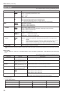
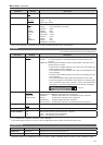
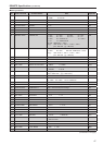
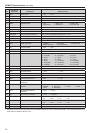
Assigned item Function Operating conditions
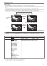
PIXEL TO PIXEL Switches screen display between input size and display
size.
Level operation
(Short-circuited: ON, Open: OFF)
FOCUS-IN-RED Displays the outlines of the subject that are in focus in
red
Level operation
(Short-circuited: ON, Open: OFF)
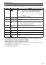
REMOTE STANDBY
*
4
*
5
Sets REMOTE STANDBY (the backlight is turned off). Level operation
(Short-circuited: ON, Open: OFF)
*
4
When remote standby is set to ON, the front power LED flashes.
*
5
If the GPI input terminal to be assigned is set to a short-circuited state first and then MENU is operated to set this item, the backlight
turns off and the screen display disappears, so MENU operation becomes unable to be checked. To change the setting of this item,
be sure to set it when the GPI input terminal is in the open state.
Restrictions
• “SD ASPECT” does not operate when the input signal is HD.
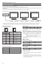
• “SD ASPECT”, “SCAN”, “WFM/VECTOR”, “MARKER”, and “PIXEL TO PIXEL” do not operate in SUB WINDOW mode.
• “SCAN” and “MARKER” do not operate in PIXEL TO PIXEL mode.
• “GAMMA SELECT”, “SD ASPECT”, “SCAN”, “MARKER”, and “MONO” do not operate when the input line of the signal is HDMI and
the signal format is 640 x 480.
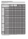
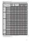
Priority of assigned functions
• When both “MARKER1” and “MARKER2” are activated at the same time, “MARKER1” has priority. However, when the display as-
pect ratio is 4:3, the “MARKER1” aspect ratio is 16:9 and the “MARKER2” aspect ratio is 4:3, “MARKER2” is displayed. In this case,
the “MARKER2” background is controlled.
• When “MARKER BACK HALF” and “MARKER BACK BLACK” are activated at the same time, “MARKER BACK BLACK” has priority.
• When “GAMMA SEL. FILM” and “GAMMA SEL. STDIO/PST” are activated at the same time, “GAMMA SEL. FILM” has priority.
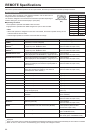
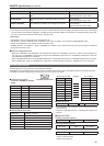
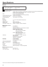
RS-232C input terminal
External operations can be performed via the RS-232C interface.
Regarding the pin arrangement and connections of the RS-232C input terminal, refer to the diagram below and the table below right.
For details on systems using RS-232C input terminal, be sure to consult your dealer.
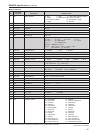
Connectors and signals
Connector: D-SUB 9-pin (female)
Signal
Pin number Signal Description
1 N.C. Not connected
2 TXD Transmission data
3 RXD Reception data
4 DSR Connected inside
5 GND Ground
6 DTR Connected inside
7 CTS Connected inside
8 RTS Connected inside
9 N.C. Not connected
Communication parameters
Signal level RS-232C compliant
Synchro system Asynchronous
Transfer rate 9600 bps
Parity None
Data length 8 bit
Stop bit 1 bit
Flow control None
Command format
STX (02h) Command : Data ETX (03h)
• The command is the 3-character string starting with STX and
ending with ETX.
• Append any data after the colon (:) following the command, as
required.
Response formats
1. Setting command response
STX (02h) Command ETX (03h)
2. Query command response
STX (02h) Data ETX (03h)
3. Error response
STX (02h) Error codes ETX (03h)
Error codes
ER001: Invalid command
ER002: Parameter error
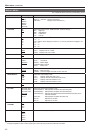
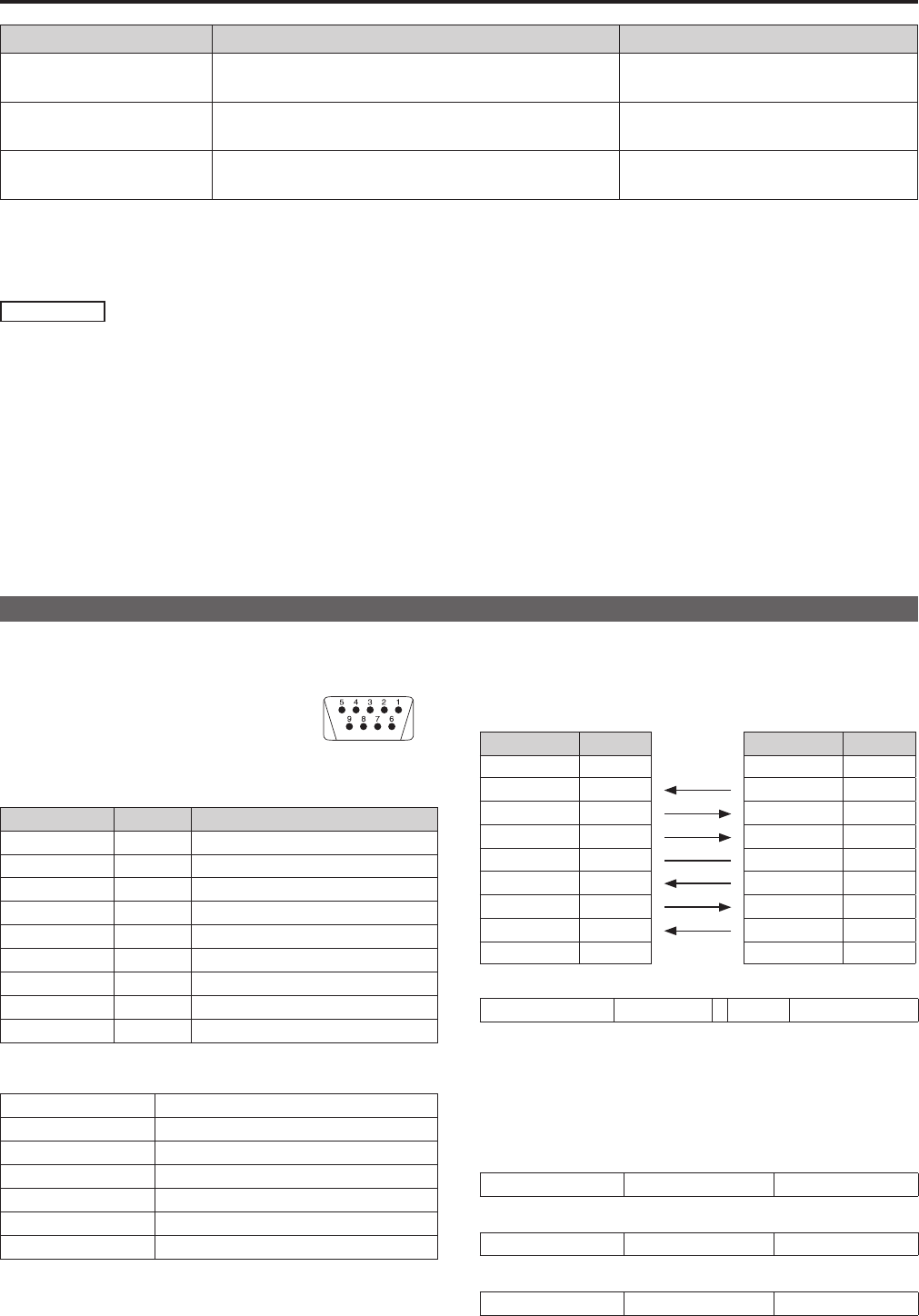
RS-232C terminals (9P)
External Device Side (Straight) This unit Side
Pin number Signal Pin number Signal
1 N.C. 1 N.C.
2 RXD
2 TXD
3 TXD
3 RXD
4 DTR
4 DSR
5 GND
5 GND
6 DSR
6 DTR
7 RTS
7 CTS
8 CTS
8 RTS
9 N.C. 9 N.C.