18
How to Use the On Screen Menu
Main menu
• For details on how to display MAIN MENU, refer to “Main
menu, FUNCTION menu, INPUT SELECT menu indications”
(→page15).
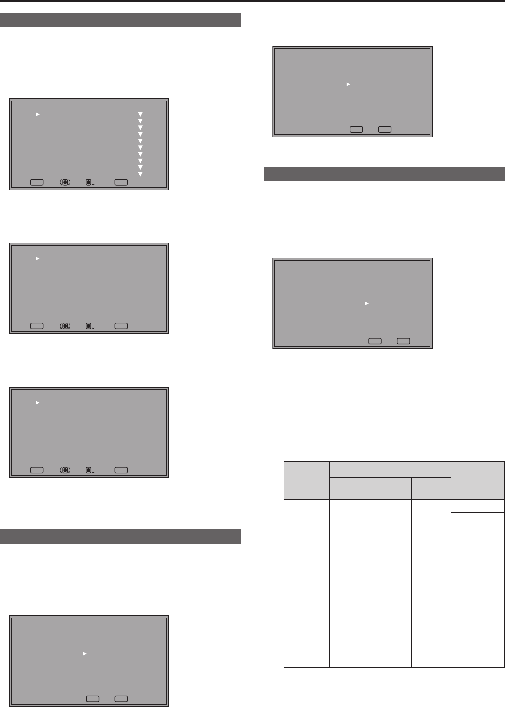
1. Turn the rotary knob to select a menu item and press the
rotary knob.
MENUEXIT
RETURN
RETURNSEL. ENTER
[MAIN MENU]
MARKER
VIDEO CONFIG
SYSTEM CONFIG
FUNCTION
GPI
INPUT SELECT
AUDIO
DISPLAY SETUP
CONTROL
HOURS METER
2. Turn the rotary knob to select a submenu and press the
rotary knob.
• The settings in the submenu change to green.
MENUEXIT
RETURN
RETURNSEL. ENTER
[MARKER]
MARKER
16:9
4:3
BACK
CENTER
CROSS
COLOR
GPI MARKER1
GPI MARKER2
OFF
4:3
OFF
NORMAL
OFF
OFF
WHITE
95%(16:9)
95%(16:9)
3. Turn the rotary knob to select a set value and press the
rotary knob.
• To cancel, press [RETURN] before pressing the rotary knob.
MENUEXIT
RETURN
RETURNSEL. ENTER
[MARKER]
MARKER
16:9
4:3
BACK
CENTER
CROSS
COLOR
GPI MARKER1
GPI MARKER2
ON
4:3
OFF
NORMAL
OFF
OFF
WHITE
95%(16:9)
95%(16:9)
4. To return to the previous screen, press [RETURN].
FUNCTION menu
• For details on how to display the FUNCTION menu, refer to
“Main menu, FUNCTION menu, INPUT SELECT menu indica-
tions” (→page15).
1. Turn the rotary knob to select a function item.
• Selected function item and set value appear in green.
MENUEXIT
RETURN
RETURN
[FUNCTION]
F1:MARKER
F2:WFM/VECTOR
F3:PIXEL TO PIXEL
F4:TIME CODE
F5:LEVEL METER
MARKER ON
2. Press the rotary knob.
• Each press of the rotary knob changes the set value and
enables function operation.
MENUEXIT
RETURN
RETURN
[FUNCTION]
F1:MARKER
F2:WFM/VECTOR
F3:PIXEL TO PIXEL
F4:TIME CODE
F5:LEVEL METER
MARKER ON
3. To return to the previous screen, press [RETURN].
INPUT SELECT menu
• For details on how to display the INPUT SELECT menu, refer
to “Main menu, FUNCTION menu, INPUT SELECT menu
indications” (→page15).
1. Turn the rotary knob to select an input signal or INT-SG
and press the rotary knob.
• To cancel, press [RETURN] before pressing the rotary knob.
MENUEXIT
RETURN
RETURN
[INPUT SELECT]
VIDEO
SDI1
SDI2
HDMI
DVI-VIDEO
INT-SG
VIDEO: Video input
SDI1 : Serial digital interface input
SDI2 : Serial digital interface input
HDMI: HDMI input (HDCP compatible)
DVI-VIDEO
*
1
: DVI-I input (HDCP compatible)
INT-SG
*
2
: Internal chart for adjustment [Color Bar +
Grayscale] (→page 55)
*
1
The name of DVI-I input terminals vary with the menu set-
ting and input signal status as shown in the table below.
Display
Menu setting (→page 38)
Input signal
status (DVI-I
terminal)
DVI-I DIGITAL
ANALOG
DVI-AUTO DIGITAL AUTO —
No input
DIGITAL
VIDEO input
present
DIGITAL
COMP. input
present
DVI-
VIDEO
DIGITAL
VIDEO
—
—
DVI-
COMP.
COMP.
YP
BPR
ANALOG —
YP
BPR
RGB-
COMP.
RGB-
COMP.
When DVI-I [DIGITAL] or DIGITAL [AUTO] is selected in a
menu, the DVI-I input terminal name is displayed only as
DVI-AUTO. INPUT NAME SETUP in the SYSTEM CONFIG
menu cannot be used to change names.
*
2
It is not possible to switch to INT-SG in a split-screen dis-
play using the SUB WINDOW function (→page 34).
2. To return to the TOP MENU screen, press [RETURN].


