


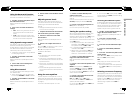
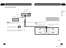
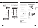
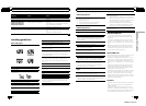

When using a display
connected to video outputs
WARNING
Never install the display in a location where it is
visible to the driver while driving.
Display with
RCA input jacks
(sold separately)
To video input
RCA cable
(sold separately)
15 cm
Video output
(VIDEO OUTPUT)
This product
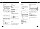
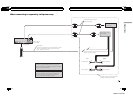
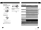
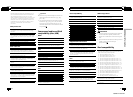
When connecting the
external video component
It is necessary to set VIDEO IN to AUX in initi-
al settings when connecting the external video
component.
External video component
(sold separately)
RCA cable
(sold
separately)
RCA cable
(sold
separately)
To video
output
To audio
output
This product
Video input
(VIDEO INPUT)
Audio input
15 cm
En
52
Section
04
Connections
Important
! Check all connections and systems before
final installation.
! Do not use unauthorized parts as this may
cause malfunctions.
! Consult your dealer if installation requires dril-
ling of holes or other modifications to the vehi-
cle.
! Do not install this unit where:
— it may interfere with operation of the vehi-
cle.
— it may cause injury to a passenger as a re-
sult of a sudden stop.
! The semiconductor laser will be damaged if it
overheats. Install this unit away from hot
places such as near the heater outlet.
! Optimum performance is obtained when the
unit is installed at an angle of less than 30°.
! To ensure proper heat dispersal when using
this unit, make sure you leave ample space
behind the rear panel and wrap any loose
cables so they are not blocking the vents
when installing the unit.
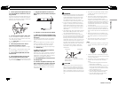
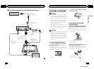
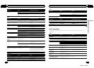
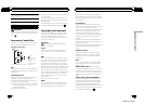
DIN front/rear mount
This unit can be properly installed using either
front-mount or rear-mount installation.
DIN Front-mount
1 Insert the mounting sleeve into the
dashboard.
For installation in shallow spaces, use the sup-
plied mounting sleeve. If there is enough
space, use the mounting sleeve that came
with the vehicle.
2 Secure the mounting sleeve by using a
screwdriver to bend the metal tabs (90°)
into place.
1
2
1 Dashboard
2 Mounting sleeve
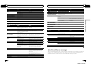
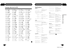
3 Install the unit as illustrated.
Use commercially available parts when instal-
ling.
1
2
3
4
5
1 Nut
2 Firewall or metal support
3 Metal strap
4 Screw
5 Screw (M4 × 8)
# Make sure that the unit is installed securely in
place. An unstable installation may cause skip-
ping or other malfunctions.
En
53
Section
05
Installation
Installation
<QRB3172-A/N>27