


r
r
t
T
l|
t
t
ll
t
t
f
f
I
I
t
t
t
t
I
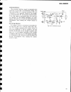
SIGNAL
lndicator
Circuit
sx-g€too
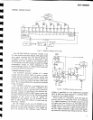
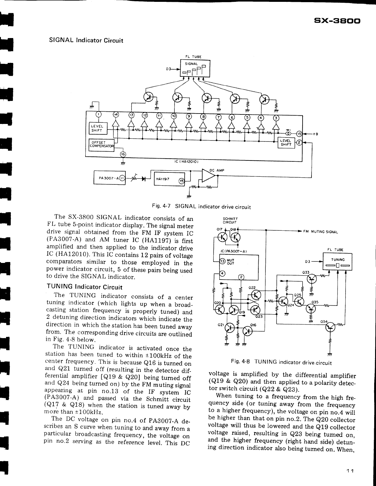
Fig.
4-7
SIGNAL
indicator
drive
circuit
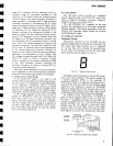
The
SX-3800
SIGNAL
indicator
consists
of
an
FL
tube
5-point
indicator
display.
The
signal
meter
drive
signal
obtained
from
the FM
IF
system
IC
(PA300?-A)
and AIVI
tuner
IC
(HA119?)
is
first
amplified
and
then
applied
to
the
indicator
drive
IC
(HA12010).
This
IC
contains
12
pairs
of voltage
comparators
similar
to
those
employed
in
the
power
indicator
circuit,
b
of
these
pairs
being
used
to
drive
the
SIGNAL
indicator.
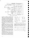
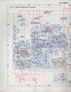
TUNING
lndicator
Circuit
The
TUNING
indicator
consists
of
a center
tuning
indicator
(which
lights
up
when
a broad-
casting
station
frequency
is
properly
tuned)
and
2
detuning
direction
indicators
which
indicate
the
direction
in
which
the
station
has
been
tuned
awav
from.
The
corresponding
drive
circuits
are
outlinei
in Fig.
4-B
below.
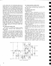
The
TUNING
indicator
is
activated
once
the
station
has
been
tuned
to within t100kHz
of
the
center
frequency.
This
is
because
e16
is
turned
on
and
Q21
turned
off
(resulting
in
the
detector
dif_
feren^tial
amplifier
le19
&
e20J
being
tumed
off
and
Q24
being
turned
on)
by
the FM
muting
signal
appearing
at
pin
no.lB
of
the
IF
system
IC
{PA3007-A) and
passed
via
the
Schmitt
circuit
(Q17
&
Q1B)
rvhen
the
station
is
tuned
away
by
more
than
t100kHz.
The
DC
voltage
on
pin
no.4
of
pAB007_A
de-
scribes
an
S
curve
when
tuning
to
and
away
from
a
particular
broadcasting
frequency,
the
voltage
on
pin
no.2
serving
as
the
reference
level.
This
DC
Fig.
4-8
TUNING
indicator
drive.circuit
voltage
is
amplified
by
the
differential
amplifier
(Q19
&
Q20)
and
then
applied
to
a
polarity
detec_
tor
switch
circuit
(eZZ
&
e2g).
When
tuning
to
a frequency
from
the
high
fre_
quency
side
(or
tuning
away
from
the
frequency
to
a
higher
frequency),
the voltage
on
pin
no.4
will
be
higher
than
that
on
pin
no.2.
The
e20
collector
voltage
will
thus
be
lowered
and
the
e1.g
collector
voltage
raised,
resulting
in
e2B
being
tumed
on,
and
the
higher
frequency
(right
hand
side)
detun-
ing
direction
indicator
also
being
turned
on.
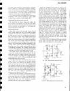
When.
SCHMITT
CIRCUII
rc
(PA30(r/-A
)