


4.
CIRCUIT
DESCRIPTIONS
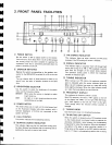
4.1
FM
TUNER
Front
End
The
FM front
end of
SX-3800 includes
a 3
ganged
tuning capacitor, a dual-gate
MOS FET-
equipped L-stage
RF
amplifier, and
a modified
Clapp circuit local oscillator.
This
oscillator
is a
voltage
controled
oscillator employing a
vari-cap
(variable
capacitance diode).
When the
quartz-lock
system
(refer
to
"Quartz-lock
system") is not in
operation,
a constant voltage is applied to the
diode.
lF Amplifier
and Detector
These employ 3
ICs
and 3 dual-element ceramic
filten. The
IC
(HA1201)
of the
first
2 stage con-
stitutes
a single-stage differential
amplifier current-
limiting limiter. The IC
(PA3007-A)
in the third
stage,an
improvement on
the former IF
system
IC
(PA3001-A),
includes an
IF limiter
amplifier,
quadrature
detector,
meter drive, and other cir-
cuits.
Performance
in terms of distortion, S/N
ratio, delay characteristics, and other
parameters,
shows a
marked improvement in comparison to
the
PA3001-4.
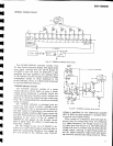
Multiplex Decoder
The recently developed multiplex decoder
IC
(PA4006-A)
combines
MPX
decoding with muting
functions in
a single
IC,
thereby handling the
functions of the more
conventional MPX IC
(PA1-001-A)
and
AF MUTING IC
(PA1002-A).
Distortion
ratings and
SIN ratio have been
further
improved by incorporating a
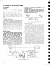
chopper type
MPX
decoder. The chopper
type switching circuit
(see
Fig.
4-1)
operates
by switching the signal
either
to
ground
or
to the through circuit, thereby
eliminating
the
generation
of unwanted
noise or
distortion.
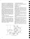
Furthermore,
since the
PA4006-A fea-
tures
DC
direct-coupled switching
with the detec-
InOut
Output
JU1IIIUIJIJUUI
.^ I
Switchins
,is".rc-1q/
-
|
thL
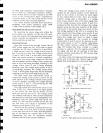
Fig.4-1 Chopper type switching
circuit
ouartz-Lock
system
The
quartz-lock
system
featured
in the SX-3800
stereo receiver
is a frequency servocontrol
system
employing a crystal
resonator.
Any displacement
in
the intermediate
frequency
(iF)
is detected
as a
DC
voltage by the discriminator
(equipped
with a
crystal resonator),
resulting
in the
local oscillator
frequency being
corrected and subsequently
locked.
This extremely stable
frequency servo-
control
system thus
ensures that
tuned frequencies
remain tuned securely
for as long as
required.
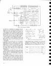
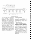
When the
IF
signal
appears
at
pin
no.l? of the
IF
system
IC
(PA300?-A),
it is amplified
and
applied
to crystal detector
(see
Fig.
4'2)
which
consists of
diodes connected
in
parallel
in
a
series
resonance
circuit
equipped
with
a crystal resona-
tor. The resonance
frequency is the same
as the
IF
frequency
(10.?MHz),
which
means
the
impedance
at this
time
will be minimal,
resulting
in the output
being reduced
to a
minimum
level.
If
the input
fre-
quency
increases, the
reactance
of
the capacitance
CRYSTAL
DTTECIOR
OC AMP
WITH LIMIiER
LPF
1
r
T
t
t
H
t
H
H
T
;
;
;
I
H
;
H
I
I
t
rl
T
clRcull
Fig.4-2
FM
quartz-lock
sYstem
tor, there is no
deterioration
in separation
at the
low frequency end.
Besides the
decoder and
muting
circuits,
the
PA4006-A
also
incorporates
the
pilot
signal
cancel-
ler,
stereo
auto selector,
VCO killer circuit,
ivluT
amplifier,
and
MUT
control
circuit.
Composite
signal
dhllL'
T
E}
FM
FRONT ENO