


8.4
FL
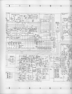
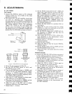
INDICATOR CIRCUIT
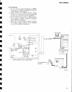
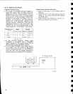
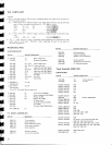
Frequency Display Circu it
o
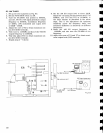
The counter
IC
(PD5009)
has been
designed to
match
FM
ceramic
filter IF offset
(caused
by
displacement of the central
frequency)
by com-
bination
of
the inputs
(of
H
or L level)
applied
to
pin
nos.3 & 4. The matching
IF
offset in the
SX-3800 is
determined according
to
the
com-
binations
of connections and disconnections
between
the
R 28 and R
28
resistors
in the
equalizer assembly
(AWM-22?).
Check
that the
combinations shown in the table below have
followed
for
the conesponding
grades
of
FM
ceramic
filters
F1
-
F3
(3
ranks
-
color coded).
If
the
SX-3800
frequency
display
reads
97.95MH2
or 98.05MH2
when a 9B.00MHz
signal
is applied
to the
receivet, adjust
TCl so
that the
display reads 98.00MH2
correctly.
If
an
accurate
9B.00MHz
input signal
source
is
not
available,
tune the
receiver
to the nearest
known
broadcasting
station
in
the 98MHz
re'
gion,
and
check
that the
station's
frequency is
correctly
displayed,
adjusting
TCl
if necessary.
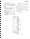
Output
Power
Indicator
Calibration
1.
Apply
a l"kHz signal to the
POWER
AMP IN
terminals.
2.
Adjusi
the level of this
input
signal so
that the
voltage
on the output
terminals
(SPEAKERS)
read 8.95V
(AC).
3.
Adjust
VR1(L)
and
VR2(R)
so
that the out-
put power
indicator read
L0
watts.
FL
indicator
assembly
F
ig. 8-5
I
I
I
FM ceramic
filter
{F1-F3}
PD5009
AVtM-227
Pin
no.3
Pin
no.4 R28(2.2n1 829(2.2n)
Red
L
H
Cut Connect
B lue
H H
Cut Cut
Orange
H
L Connect Cut
H=5.5V, L:OV
vR2*€)
@_vnr