


ic
('tA73t8P)
t/?
HOLO
&
OC AMP
L€VE L
SHIF I
OFFSET
COM.
PENSAIOR
t
t
t
H
r|
I
t
t
t
t
I
H
I
t
H
I
I
t
I
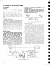
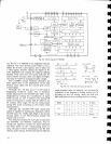
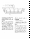
Fig.
4-12
Power
indicator
circuit
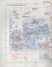
4.7
POWER
]NDICATOR CIRCUIT
s16NAL
rN
o*-l
F/LAMENT
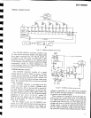
The
SX-3800
output
power
indicators feature
fluorescent
indicator
tube
(FL
tube).
In
this tube,
thermionic emissions
from the
cathode are ac-
celerated
into the
fluorescent
substance
of the
segmental
anodes, resulting
in the emission
of
light.
This tube is used to indicate
numerals, letters,
and
other
symbols.
An
outline of
the
FL
tube drive
circuit is shown
in
Fig.
4-12.
The
output
circuit sj"tnal is applied to
pin
no.6
(
)
of the
IC
(TA?318f
-A).
The
IC
con-
tains
a detector
circuit, conpressor
(40d8),
and
peak
hold circuit
for both
left
and right
channels.
The dynamic
range of
the
signal
is thus contracted
by
40dB to obtain a
"peak
held"
DC voltage.
The
output
pou'er
indicator
segments of
tire
FL
tube are driven by
the
HA12010 ICs
(one
for each
channel)
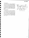
equipped
rvith 12
pairs
of
differential
amplifiers. These amplifiers
are biased at increasing
levels,
so each amplifier
lvill
commence
to
operate
separately as the
input level increases.
And
since
these
amplifiers apply
the
voltages
to the output
power
indicator
segmetrts, each
successive segment
will
light
up in turn as
the input level rises.
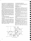
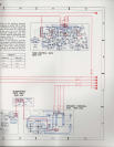
4.8
PROTECTION
CIRCUIT
The
purpose
of
this circuit is to
protect
the
speakers
and the
power
amplifiers.
The relay in
the
output circuit is
automatically
opened
in
any of
the following cases:
L.
During
the
"transient
operations"
lvhen
the
power
supply is turned on and off.
2. Upon detection
of an overload,
caused by
a
short circuit in the
ioad.
3. Upon detection of a
DC
voltage
in the output
caused by component failure or accident.
Muting
Operation when
Power
Supply is Turned
On and Off
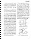
With
reference
to
Fig.
4-13 when the
porver
supply is
turned on,
Q3
turns off due
to
*81
(l'he
time constant
of the
*81
circuit is
very
sma11.).
If
there is
no input
(DC)
on
Qb
and
Q6,
they will
be
off, and the timing capacitor C1 charges
up
through R8
and R6, and thus
Q4
turns
on.
\Vhen
Q4
condr,rcts,
tire
relay
operates, and the output
muting
on the
power
amplifier
will be
removed.
When
the
polver
supply is
turned
off,
-81
rvill
abruptly decay, and
Q3
will conduct
owing
to the
resiclual component of
+81.
As a result, C1
rvill
rapidly
discharge,
Q4
will
cease to conduct, rvhere-
upon
the relay will become de-energized and
restore
mnting.
14