


J
r
F
T
r
r
T
T
T
I
I
t
T
T
I
I
I
I
I
I
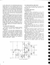
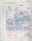
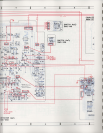
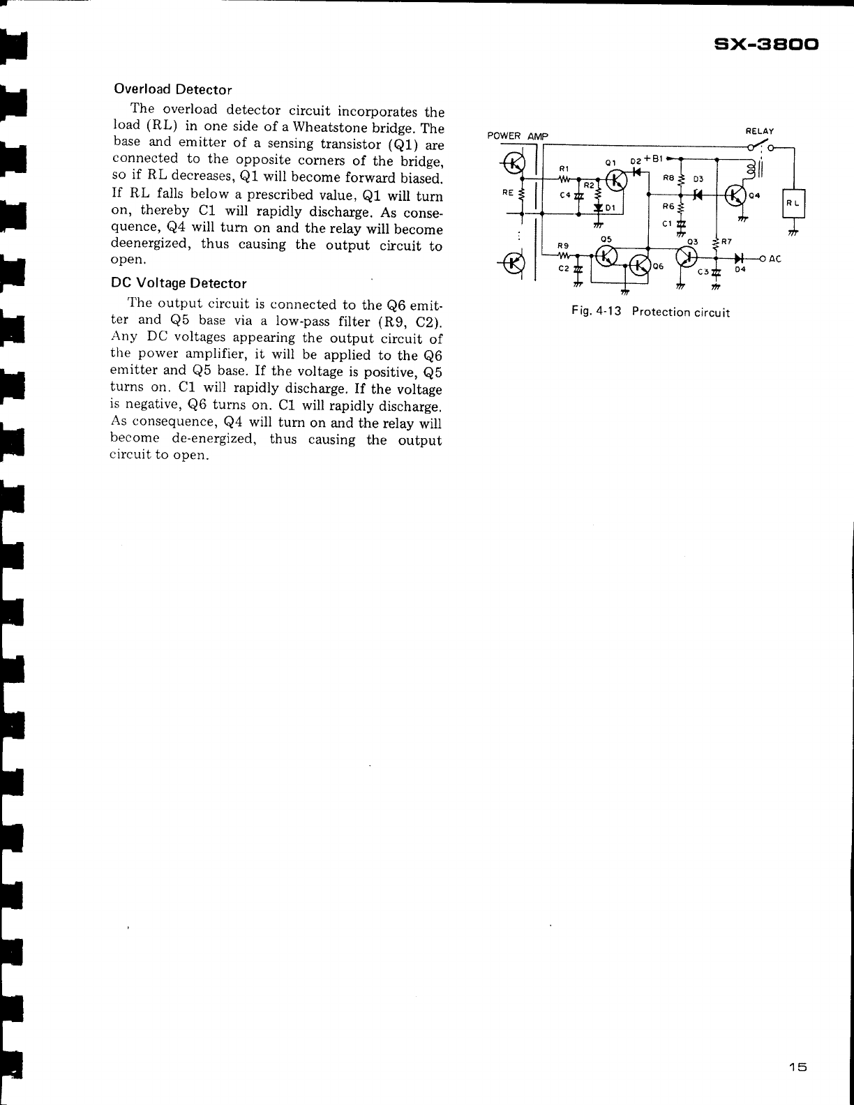
Overload
Detector
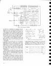
The
overload
detector
circuit
incorporates
the
load (RL)
in one
side
of a Wheatstone
bridge.
The
base
and
emitter
of
a sensing
transistor (e1)
are
connected
to
the
opposite
corners
of
the
bridge,
so if
RL
decreases,
Q1
will
become
forward
biased.
If
RL falls
below
a
prescribed
value,
e1
will
turn
on,
thereby
C1 will
rapidly
discharge.
As
conse-
quence,
Q4
will
turr
on and
the relay
will
become
deenergized,
thus
causing
the
output
circuit
to
open.
DC Voltage
Detector
The
output
circuit
is
connected
to
the
e6
emit-
ler
and
Q5
base
via
a low-pass
filter
(Rg,
C2).
Any
DC
voltages
appearing
the
output
circuit
of
the
porver
amplifier,
it
wil]
be applied
to
the
e6
emitter
and
Q5
base.
If
the voltage
is
positive,
eb
turns
on.
C1
will rapidly
discharge.
If
the
voltage
is
negative,
Q6
turns
on.
C1 will
rapidly
discharge.
As
conseqnence,
Q4
will
turn
on
and
the relay
will
become
de-energized,
thus
causing
the
ourpur
circuit
to open.
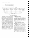
six-gaoo
F
ig.
4-
1 3
Protection
circu
ir
15