


Part
No.
t
I
t
T
t
t
t
t
;
t
t
;
il
t
t
t
il
I
t
;
Symbol
& Description
Part
No,
ATF-106r
ATF,OB9
ATF.1O5
ATF.O38
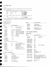
SEMICONDUCTORS
Part
No.
Symbol
&
Description
F1-F3
FM
ceramic fitter
F4,
FS
FM
low-pass
f
itter
F6
AM
ceramic firrer
F7
AM 455kHz f
ilter
CKDYF 1032
50
CQMA 153K
50
coMA 473J
50
cosH
331J 50
cosH
152J
50
CEANL R22M
50
CEANL
OlOM 50
CEANL
2R2M 50
coMA
1 53K 50
CEA
OlOM
sOL
CEA 3R3M 50L
CEA 4R7M
50L
CEA lOOM
sOL
CEA
22OM 25L
CEA 47OM 1OL
cEA
101M
t0L
CEA
lOIM
25L
CEA
221M
16L
CEA 331M
1OL
CEA 471M 16L
CEA
47OM
25L
Nole:
RESISTORS
Part
No.
uco
?141
c53
voo
c55, C57
nlna
c65, C66, C70,
C71
c63, C64
c303,
c304
?14
c79,
CgB
c97
c33, C43, C69
cB0
c30,
c76, c77
c36, CB3,
C84
c12
c54
c51
,
c85
c3,
c4,
c78
llhen
ordering resrsfom,
conuert
the
resistance
ualue
into code
form,
and
then
rewrite
tlze
part
no. as
before.
Symbol & Description
35K73
2SK34
2SK 1
68
zSC1
906
2SA535-A
HA120'l
NJM4558DV
PA3007-A
PA4006-A
HA',l
197
zSC1
91 9
2SC2575
{2SC945A)
2SA1
100
(25A733A)
HA1
201
0
MZ-061
(wz-0611
tDt535
{'152473','
1SV69-03
OTHERS
o1
02
03,
o1
5
o4
06,
07, 09
O8
010
01
1
o12
nra
014,
016-021
,Q24*A26
o22,423,
O2B-O35
Dl, 02
D3, Ds*D17
D18
RD%PM
NNN
J
RD%PM t]NrJ J
RD/1PM
LINN
J
ij
RD%PMF
nnn J
RN%SO
nnlrn
F
c92-048
c92-049
ACP-056
ACP-055
ACV-18'l
ATE.OOS
ATE.045
ATB-063
ATB-069
ATC"097
T24"O28
Symbol & Description
R1-R11,
Rr3, R15-F19,R21
,R22,
R24-n29,
R3 1
-R45
R47-R53,
R56-R59,
R61, R63. R65,
R67-R99,
F101-R125
R128*8140.
R301-R316
FI 1? R'N
R30
VR1
VR2
VR4
VR5
VR6
R46, R126
Semi-fixed 47k
Semi-fixed 10k
Semi-f
ixed
22k
SemiJixed
6.Bk
Variable
100k
(VOLUME)
Variable
1M
(BALANCE)
Part
No.
Symbol & Description
ASX-130
ASK-r 52
AKA.O13
AKB-063
s1, s2
s3, s4
Remote
lever
swrtch
(TAoE
)
Lever
switch
(MUTING,
LOUDNESS)
Terminal
{ANTENNA}
Terminal
(TAPE)
ACT-021
VR7
TRANSFORMERS,
COILS
AND FILTEBS
Part
No.
9vlrrl
T1
T2
IJ
T4
L2
L3, L7,
& Description
Arc-o72
L8
FM
IFT
FM DET
transformer
AM OSC
coil
AM lF
coil
FM
antenna
coil
L9-L13,
L15
RF
coil
FM
OSC coil
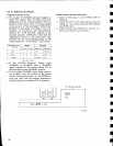
Precautions
t
The
FIqI
ceramic
filters
(ATF.106,
symbol
nos.Ft
-
F'3)
in
the
tuner
assembly
(GWE.
j3J)
hos
been
selected
on
the
basis of their respective
IF
offset ualues (the
degree
of displacement
from
the center
lF). Filters
are
graded.
into
3
ranhs,
these being
identified
b5' color
coding nt
the
top
(red,
orange, and.
blue). When replacing
filters,
always
use
filterc
of the
same color
code.
When
placing
arder$
for
these
filters,
designate
the
grad,e
(color)
as
well as the
part
no.
t
The crystal
resonator (ASS-012,
syntbol no.Xl) in
lhe
detector
assembly
(G\VX-463)
is
auailable in
3 different
types
coffespanding
to the
IF
offset ualues
of the Ittrf
ceramic
filters
(ATF-L06,
symbol nos.F.l
-F3)
in
the
tuner
assembly
(GWE-133).
These
may be
identified
by
the
different
colored
dots
(red,
blue,
orange) at the
head.
When replacing
crystal resonators,
chech lhat the
color
is
some as the
ceramic
filters.
4A