


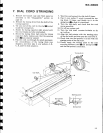

H
H
H
T
H
T
T
T
T
H
FI
I
t
t
I
t
t
I
r
r
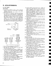
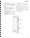
8,3
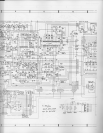
POWER
AMPLIFIER
'I'urn
VR3,
VRb
(L)
and VR4,
VR6
(R)
fulty
around
in
the counter-clockwise
direction,
but
set
VR1(L)
and
VR2
(R)
to
the
center
positions.
With-
out
any load
or input
signal,
turn
the
POWER
switch ON.
DC Balance
1.
Adjust
VR1(L)
for
0V
(to
within
t30mV)
be-
tween
terminal no.23
and
ground.
2. Adjust
VR2
(R)
for
0V
(to
within
t30mV)
be-
tween
terminal
no.22
and
ground.
ldle
Current
sx-3Cloo
^ \' -
|
,*o,-,{'
"*.u
{
,fJaJtuL6
t
ku
/o.n
4.
?,^.
or
^aA.f
h.,r,z--"{*(
(_nry'l)
n
aFosc,lt
,-
d P
**
i+>
u
t
{,-L
r-
/.o.'J
?oir,
**
Q(s,)
o,--"
J
Pos
*
r.r#
+t*<r'.-'U(
{-n"Li,^.g^.
\
,v\
ut
*
j,
t,t
e
;,t;
.-1.*.1.
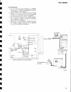
1.
;\djusl
VRB
(L)
for
120mV
no,28(+)
and no.25(-).
2.
Adjust
VR4(R)
for
120mV
no.17(+) and no.20(*).
3.
Adjust
VR5(L)
for
150nrV
no.28
and no.25.
4.
Adjust
VR6(R) for
150mV
no.1?
and no.20.
between
terminals
between
terminals
between
terminals
between
terminals
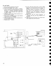
No.1
7
No.20
No.22
No.23
No.25
No.28
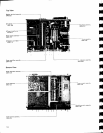
R
t*
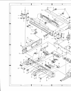
Power
amplifier
assembly
R
t\
I
:
I
I
I
i
I
I
I
-_L
>'
t-r(2t
VR6
II
ltl
@U
u*o
ll
IU
{a)
{I))}
VR2
llL
Itt-
l[
VR1
*.
b
tf|
vR3ll
@n
||l
vR5ll
t!
I
)6f
Fis.
8-4
e3