


8.
ADJUSTMENTS
8.1
FM
TUNER
FM
Tracking
r
Connect
the SIGNAL
meter
or DC
between R100
(no.? pin
of
Q8)
on
assembly
and
ground.
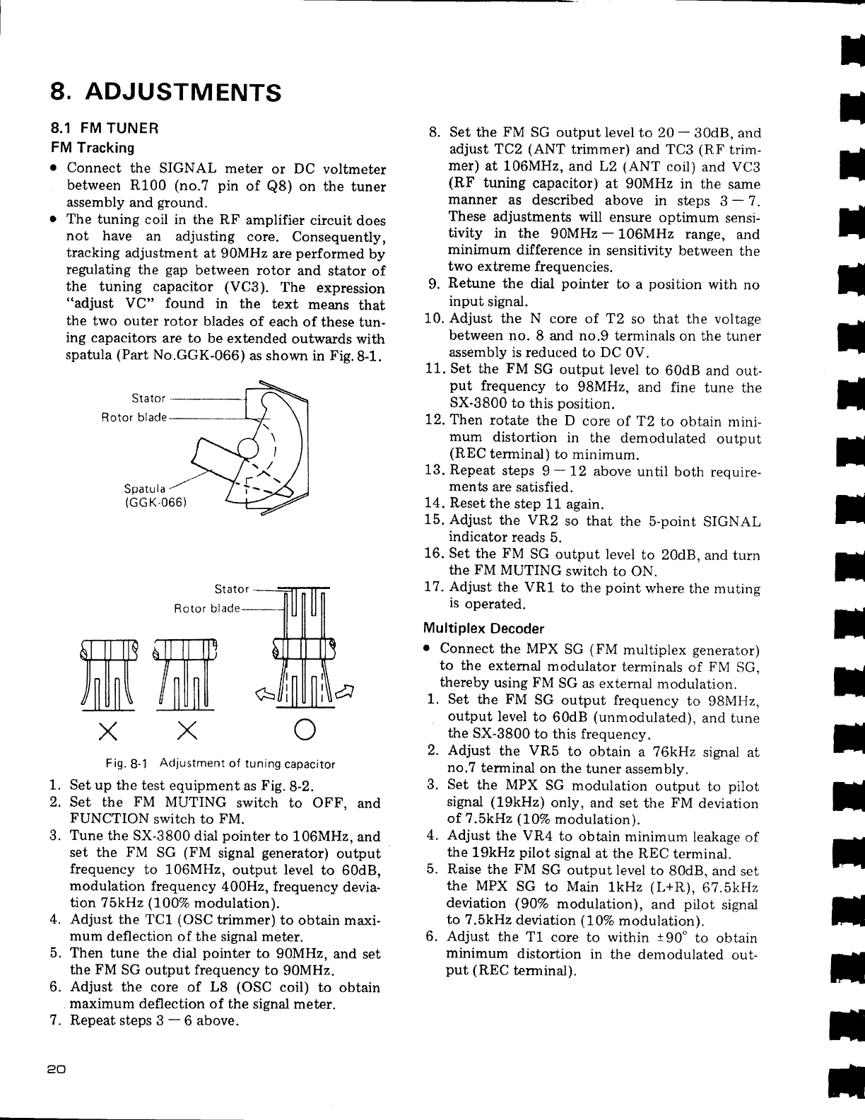
r
The tuning
coil in the RF
amplifier
circuit
does
not have
an
adjusting core.
Consequently,
tracking
adjustment
at 90MHz
are
performed
by
regulating
the
gap
between
rotor
and
stator of
the tuning capacitor
(VC3).
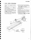
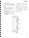
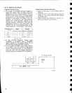
The
expression
"adjust
VC" found
in the
text
means
that
the
two outer rotor
blades
of each
of these
tun-
ing
capacitors
are to be
extended
outwards
with
spatula
(Part
No.GGK-066)
as shown
in
Fig.8-1.
Spatu
I
a
(GG
K.066)
fie161
glsds-
Fig.
8-1
Adjustment
of tuning
capacitor
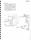
Set up
the test equipment
as
Fig.8-2.
Set
the
FM
MUTING
switch
to
OFF,
and
FUNCTION
switch to
FM.
Tune
the SX-3800
dial
pointer
to 106MHz.
and
set
the
FM
SC
(FM
signal
generator)
output
frequency
to 106MHz,
output level
to
60d8,
modulation
frequency
400H2, frequency
devia-
tion
75kHz
(100Vo
modulation).
Adjust
the TC1
(OSC
trimmer)
to obtain maxi-
mum
deflection
of the
signal meter.
Then
tune the dial
pointer
to
90MHz, and
set
the FM
SG output
frequency
to
90MHz.
Adjust
the core of
L8
(OSC
coil) to
obtain
maximum
deflection of the
signal meter.
RepeatstepsS-6above.
8.
Set
the
FM
SG output
level to
20
-
30d8, and
adjust TCz
(ANT
trimmer)
and TC3
(RF
trim-
mer)
at L06MHz,
and L2
(ANT
coil) and VCB
(RF
tuning
capacitor)
at
90MHz in the
same
manner
as described
above in
steps
3
-
?.
These
adjustments
will ensure
optimum
sensi-
tivity
in the
90MHz
-
106MHz range,
and
minimum
difference in
sensitivity
between
the
two extreme
frequencies.
9.
Retune
the
dial
pointer
to
a
position
with
no
input
signal.
10.
Adjust
the
N
core of T2
so that the
voltage
between
no. 8 and no.9
terminals on the tuner
assembly is
reduced to DC 0V.
11.
Set
the
FM
SG output
level
to 60dB
and
out-
put
frequency
to
9BMHz,
and
fine
tune the
SX-3800
to this
position.
12.
Then
rotate
the D
core
of
"t2
to obtain
mini-
mum
distortion
in
the
demodulated
output
(REC
terminal)
to
minimum.
13. Repeat
steps
g
-
12 above
until
both
require-
ments
are
satisfied.
1.4.
Reset
the
step
11" again.
15. Adjust
the VR2
so that
the 5-point
SIGNAL
indicator
reads
5.
16. Set
the
FM
SG output level
to 20d8,
and turn
the
FM
MUTING
switch to ON.
L7. Adjust
the VR1
to
the
point
where
the mutins
is
operated.
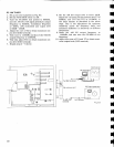
Multiplex
Decoder
I
Connect
the MPX
SG
(FM
multiplex
generator)
to the
extemal
modulator
terminals
of
FNI
SG,
thereby
using FM
SG
as extemal
modulation.
1. Set
the
FM
SG
output frequency
to
gBIVIHz,
output
level
to
60dB
(unmodulated),
and
tune
the
SX-3800
to this
frequency.
2.
Adjust
the VRb
to obtain
a 76kWz
signai at
no.7
terminal
on
the tuner
assembly.
3.
Set
the MPX
SG
modulation
output
to
pilot
signal
(19kHz)
only, and
set the
FM
deviation
of ?.5kHz
(107c
modulation).
4.
Adjust
the
VR4
to
obtain
minimum
leakage
of
the
19kHz
pilot
signal at
the
REC
terminal.
5. Raise
the
FM
SG
output level to
80d8,
and set
the
MPX
SG to Main
lkHz
(L+R),
6?.5kHz
deviation (907o
modulation),
and
pilot
signal
to
7.5kHz
deviation
(107o
modulation).
6.
Adjust
the T1
core
to
within
tg0"
to
obtain
minimum
distortion
in the
dernodulated
out-
put
(REC
terminal).
voltmeter
the tuner
I
t
t
H
t
I
t
t
t
t
t
t
t
I
;
t
il
t
rl
arrrrTl!
U'LIFIP
/nllnll
/
llll llll
X
ffi
X
1.
2.
iJ.
5.
6.
q
,.
Botor
blacle