


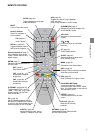

STARTUP GUIDANCE
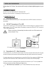
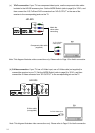
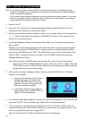
connector, use a Mini D-Sub 15-pin cable (not supplied) to connect the receiver to your TV. Set
the MODE-Switch (refer to page 8) to RGB, and then connect the RGB connector on the rear
of the receiver to the corresponding socket on the TV.
Do not connect any PC monitor to the receiver via Mini D-Sub 15-pin cable.
Some HD-ready TV may not display some specific video format via Mini D-Sub 15-pin video
connection. In this case, please press V.FORMAT button to change to an appropriate fixed
format. (For more details, please refer to Appendix 2 System Setup Table in page 50).
HD OUTPUT
RGB
YP
B
P
R
MODE
Y /G
P
B
/B
P
R
/R
HD
VD
RGB
SERIAL PORT
SD OUTPUT
S-VIDEO
L
R
L
R
VIDEO
Mini D-Sub 15-pin video cable
(not supplied)
To TV Mini D-Sub 15-pin
video input
HD-S25
DIGITAL
(COAXIAL)
(OPTICAL)
AUDIO
Note: This diagram illustrates video connections only. Please refer to Page 15 for Audio connection.
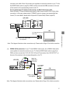
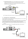
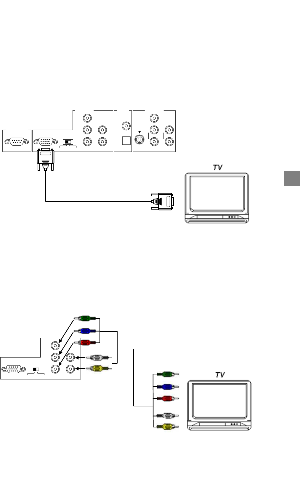
(b) RGBHV (RCA) connection: If your TV has RGBHV video inputs, use a RGBHV video cable
(not supplied) to connect the receiver to your TV. Set the MODE-Switch (refer to page 8) to
RGB, and then connect the Y/G, P
B
/B, P
R
/R, HD and VD connectors from “HD OUTPUT” on
the rear of the receiver to the corresponding jacks on the TV.
RGBHV video cable
(not supplied)
To TV RGBHV
video inputs
G
B
R
HD
VD
HD
VD
G
B
R
HD-S25
Match the
colors when
connecting
HD OUTPUT
RGB
YP
B
P
R
MODE
Y /G
P
B
/B
P
R
/R
HD
VD
RGB
Note: This diagram illustrates video connections only. Please refer to Page 15 for Audio connection.
13