


STARTUP GUIDANCE
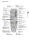
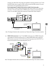
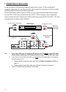
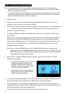
(e) Composite video connection: If your TV has composite video inputs, use the yellow
connector of the Audio/Video cable included in the HD-S25 accessory box. Set the
MODE-Switch (refer to page 8) to YP
B
P
R
, and then connect the yellow video connector from
“SD OUTPUT” to the corresponding jack on the TV.
SD OUTPUT
S-VIDEO
L
R
L
R
VIDEO
HD OUTPUT
RGB
YP
B
P
R
MODE
Y /G
P
B
/B
P
R
/R
HD
VD
RGB
DIGITAL
(COAXIAL)
(OPTICAL)
AUDIO
Audio/Video cable
(supplied)
To TV composite
video input
HD-S25
Match the
colors when
connecting
Note: This diagram illustrates video connections only. Please refer to Audio connection below.
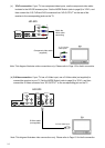
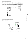
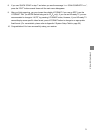
1-4. Connections to TV – Audio Connection
For audio connections, you have two choices. You can connect the receiver to your TV or to an audio
amplifier equipped with a Dolby® Digital decoder.
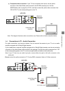
If you do not have an external amplifier equipped with a Dolby® Digital decoder, use the red and white
connectors of the Audio/Video cable included in the package. Connect the audio connectors from “L/R”
to the corresponding jacks on the TV: red to red (right audio) and white to white (left audio).
Note: If your TV has only one audio input jack, connect either the right or left audio connector to the
audio jack.
Do not connect the yellow connector to TV if using RGB, component video or S-Video connector.
SD OUTPUT
S-VIDEO
L
R
L
R
VIDEO
HD OUTPUT
RGB
YP
B
P
R
MODE
Y /G
P
B
/B
P
R
/R
HD
VD
RGB
DIGITAL
(COAXIAL)
(OPTICAL)
AUDIO
Audio/Video cable
(supplied)
To TV audio inputs
white
red
HD-S25
white
red
Match the
colors when
connecting
15