


DSM 132/132RS Receiver User Guide 99
Cables and Connectors B
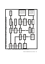
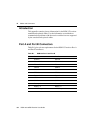
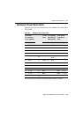
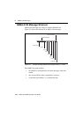
B.4 Standard Power/Data Cable
Table B.2 gives pin-out information for the standard power/data cable
(PN 30945).
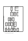
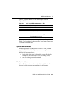
Table B.2 Standard power/data cable
To receiver
P1 connector
12-pin (female)
7 cond
cable
To computer
P2 connector
DE9 (female)
To DC power
2 conductor
cable
Pin Signal Color Pin Signal Color Signal
1 Event In
←
Black 4 DTR
2TXD
→
Orange 2 RXD
3RXD
←
Red 3 TXD
4
5 SIG GND
↔
Shield 5 SIG
GND
6RTS
→
Yellow 8 RTS
8CTS
←
Green 7 CTS
9
7
1
1
Pins 7 and 10 of the P1 connector are jumpered with a 5 kOhm, 5% resistor
PWR ON
←
10
1
V+ IN
←
Red Red V+ IN
11 V– IN
←
Black Black V– OUT
12 PPS
→
Blue 9 PPS