


9 10
Getting Started With Setting Up Your TV Getting Started With Setting Up Your TV
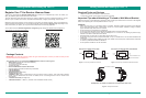
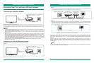
Important Tips about Lifting and Moving the TV Installing a Wall Mount Bracket (not included)
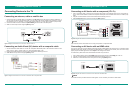
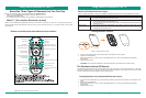
Locating Ports and Buttons on Your VIDAA Smart TV
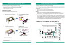
Attaching the TV Stand
• We recommend that at least 2 people are available to lift and transport the TV.
• Before moving or lifting the TV, disconnect the power cord and all cables.
• When holding the TV, face the screen away from you to avoid damage.
• Hold the top and bottom of the TV firmly.
Your TV can be mounted on a wall using a wall mount bracket (not supplied) that can be purchased separately.
Before you begin the installation instructions provided by the wall mount manufacturer, we suggest that you do the
following things:
1. Remove the TV stand if you already attached it.
2. Place the TV face down on a clean, safe and cushioned surface.
3. Place the spacers (not included) in the corresponding bracket holes.
CAUTION
• Be sure to use the provider spacers between the TV and the bracket when attaching the mount.
• To prevent internal damage to the TV and ensure it is mounted securely, be sure to use fixing screws (not
provided) that are 9.5 - 11.5 mm in length when measured from the attaching surface of the mounting hook.
Follow instructions provided with the Wall-Mount bracket.
• If you are not sure of your ability to complete the installation, contact a professional installer or service
technician for assistance. Hisense is not responsible for any damages or injuries that occur due to mishandling
or incorrect assembly.
• The selected screws are 9.5 - 11.5 mm in length when measured from the attaching surface of the TV’s rear
cover. The diameter and length of the screws differ depending on the Wall-Mount Bracket model.
Follow the steps and illustrations below to attach the stand.
Figure 4. Stand Installation steps
Figure 5. Ports and buttons on Your TV
a. Secure the STAND COVER to the STAND
COLUMN with 4 screws.
b. Insert 2 (ST4) screws in the front and 2
(M5) screws in the back.
a. Align the BASE STAND with the screw
holes located on the bottom of the TV.
b. Secure the BASE STAND to the TV with
the four screws tightly.
BASE STAND
TV BACK
M5×12mm
SCREWS
Carefully place your TV on a soft, cushioned,
surface to prevent damage to the screen.
M5 x 12mm
Secure the STAND COLUMN to the BASE
with four screws
.
BASE
STAND COLUMN
SCREWS
STAND COVER
STAND COLUMN
SCREWS
STAND COVER
STAND COLUMN
M5×12mm
1. 2.
3.
4.
Power input
TV Bottom View
TV Side View
Button View
HDMI2HDMI3HDMI4
IR BLASTER
LAN
PC/DVI
AUDIO IN
PC IN
MUTE
INPUT
CH
CH
VIDEO
AV IN
L R
HDMI1
ANT/CABLE IN
DC 5V 0.5A(MAX)
USBUSB
DC 5V 0.5A(MAX)
USB
Y P
B
P
R
COMPONENT IN
Documentation Disclaimer: Images throughout this manual are for illustrative purposes only and may differ
from the actual product.