


16
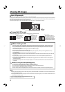
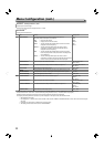
Other 3D functions
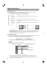
You can display the wave form monitor or vector scope, and compare and check the SDI IN 1/L and SDI IN 2/R input signals.
● Works in MIX mode. The operation to be performed differs in other modes. (→ page 9)
● Each time you press the SCOPE button, the display mode changes in the following order.
No display : Does not display the wave form monitor/vector scope.
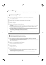
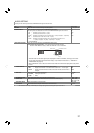
Parallel wave form
monitor
: Tiles the wave form monitors of the images input into the SDI IN 1/L and SDI IN 2/R terminals.
Parallel vector scope : Tiles the vector scopes of the images input into the SDI IN 1/L and SDI IN 2/R terminals.
Difference wave form
monitor
: Select this to display the differential of the signals from the SDI IN 1/L and SDI IN 2/R terminals in
wave form monitor.
Difference vector
scope
:
Select this to display the differential of the signals from the SDI IN 1/L and SDI IN 2/R terminals in
vector scope.
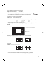
Y Y
Y
Parallel wave form monitor Parallel vector scope Difference wave form monitor Difference vector scope
• When the CAMERA ASSIST MENU “LR SWAP” is set to “ON”, L and R images of the parallel wave form monitor and vector scope are
exchanged and then displayed.
• The positions of the wave form monitor and vector scope can be changed in “POSITION” under the MAIN MENU “SCOPE SETTING.”
• The wave form monitor and vector scope are not displayed in “R SHIFT” or “ANAGLYPH” of the CAMERA ASSIST MENU.
• The vector scope is not displayed when the input signals are RGB.
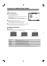
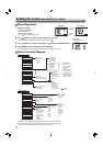
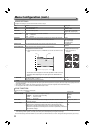
When 3D is “ON”, the L and R lines measuring the visual difference between L and R images, and the pixels and percentage between the
lines, are displayed. The following two modes are available for the line display: “Cursor mode” and “Grid mode.”
● Each time you press the 3D CURSOR button, the line display mode changes in the following order.
No display Cursor mode
Grid mode
● The information (→ page 10) and SCOPE are not displayed in “Cursor mode” or “Grid mode.”
● The positions of the pixels and percentage can be changed in “POSITION” under the MAIN MENU “INFORMATION.”
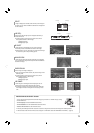
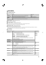
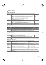
Cursor mode
The L, R, and H lines appear, which measure the visual difference.
● The H and L lines are fined dotted lines, and the R line a coarse dotted line. The selected line is displayed as a solid line.
● The line color changes when the line goes beyond “FAR LIMIT” or “NEAR LIMIT” under the MAIN MENU “3D SETTING.”
● The ratio of the difference between the L and R lines to the horizontal pixels appears in the percentage display.
● In the percentage display, “+” indicates the pop-up level (when the L line is placed on the right of the R line), and “–” the depth
(when the L line is placed on the left of the R line).
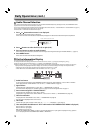
SCOPE button/lamp
3D CURSOR button/lamp
H line (Group B)
H line (Group A)
(selected line)
Pixels/Percentage between L and R lines
L line (Group A)
R line (Group A)
R line (Group B) L line (Group B)
-