


ķ
12
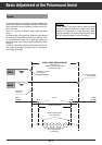
Setting the Zero Position and Limits
Driving the exactly mounted aerial to the east
end stop
Before setting the limits L1 (East) and L2 (West), it is absolu-
tely necessary that the aerial has been driven to its mechani-
cal east end stop for setting the internal counter to zero.
The aerial must be mounted in such a way that no obstruc-
tions (trees, walls, etc.) can hinder its travel to its east end
position.
Follow these steps:
Switch the unit on.
Press the
¢
ʐ button 3 times.
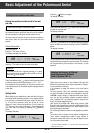
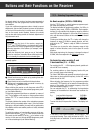
The display indicates, for example:
Press the
¢
<
button to drive the aerial to the east.
Press and hold down the
¢
<
button until the east end stop
is reached, giving the following indication: "
EAST END
".
This represents the zero position of the internal counter and
is the reference point for all satellite positions programmed at
a later date.
Setting limits
When searching new satellites at a later date with the help of
the manual aerial positioning function, it may happen that the
limit switches or mechanical end stops (crash) are often run
to. To avoid this, electronic limits can be set at a short
distance in front of these end positions. For this, press the
¢
>
button to let run the aerial approx. 20 impulses to the
west, then store the setting by pressing the
¢
MEMORY
button.
The display indicates:
TIMER
opü+
I99 XLIMITX1
STEREO
SIGNAL IIIIIIIIIIIII
Attention:
If the aerial should run in opposite direction, it is neces-
sary to exchange the connections M1 and M2 on the ter-
minal strip
wU
of the receiver.
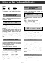
TIMER
opü+
I99 XL1XX414
STEREO
SIGNAL IIIIIIIIIIIII
It is absolutely necessary to execute this step.
Press the
¢
ʐʐ
button once again.
The display indicates:
Press and hold down the
¢
>
button until the aerial has
reached its west end stop.
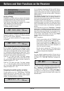
The display indicates:
Press the
¢
<
button to let run the aerial approx. 20 impul-
ses to the east, then store the setting with the
¢
MEMORY
button.
The display indicates:
You can connect to the receiver motors delivering max. 7999
impulses between the east and west end stops. The impulses
can be generated by Reed contacts, Hall sensors, or opto
couplers.
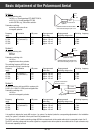
Adapting the Receiver to Different
Aerial Systems with Different
Feed-in Systems (LNC´s).
Today, there exist a variety of very different LNC types with
different local oscillators and control commands for frequen-
cy and polarization switching.
It is necessary to adapt the receiver to the used feed-in
system.
For rotary systems, LNC´s with switchable frequency range
are used. Polarization switching can be effected by means of
a 14/18V* supply voltage or magnetic/motor-driven polari-
zers. You can also use feed-in systems (reception systems)
with 2 separate LNC´s for different frequency ranges (inclu-
ding a wave-guide separating filter).
Your receiver is provided with 2 aerial inputs (Input A, Input
B) which make it possible to connect an additional aerial (for
example, permanently pointing at the Astra satellite, which
then is permanently available).
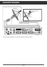
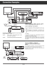
The following illustrations show several application possibili-
ties.
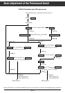
The receiver offers a choice of three system configurations.
These system configurations enable a large number of
connection variants and make it very easy to adapt the recei-
ver to the aerial system used.
* 14/18 V LNC individually adaptable by ± 2 V (see
wT
in section "Receiver Buttons and
Connections / Rear of unit).
TIMER
opü+
I99 XLIMITX2
STEREO
SIGNAL IIIIIIIIIIIII
TIMER
opü+
I99 WESTXEND
STEREO
SIGNAL IIIIIIIIIIIII
TIMER
opü+
I99 XL2XXX20
STEREO
SIGNAL IIIIIIIIIIIII
Basic Adjustment of the Polarmount Aerial