


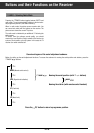

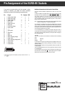


Pin Assignment of the EURO-AV Sockets
Additional Information for Units sold in Great Britain
Units sold in GB are suitable for operation from a 240 V AC, 50 Hz mains
supply.
In case this appliance is supplied with a Safety Standard Approved mains
lead fitted with a non-rewireable 13 Amp mains plug which, if unsuitable for
your socket, should be cut off and an appropriate plug fitted by a
qualified electrician. The fuse and fuse holder must be removed from the
plug as accidental insertion of the redundant plug into a 13 Amp socket is
likely to cause an electrical hazard.
Note: The severed plug must be destroyed to avoid a possible shock hazard
should it be inserted into a 13 Amp socket elsewhere.
If it is necessary to change the fuse in the non-rewireable plug, the correct
type and rating (5 Amp ASTA or BSI approved BS 1362) must be used and
the fuse cover must be refitted. If the fuse cover is lost or damaged the lead
and plug must not be used until a replacement is obtained. Replacement fuse
covers should be obtained from your dealer.
If a non-rewireable plug or a rewireable 13 Amp (BS 1363) plug is used, it
must be fitted with a 5 Amp ASTA or BSI approved BS 1362 fuse. If any other
type of plug is used it must be protected by a 5 Amp fuse either in the plug or
at the distribution board.
Important:
The wires in the mains lead are coloured in accordance with the following
code:
BLUE – NEUTRAL
BROWN – LIVE
As the colours of the wires in the mains lead of your appliance may not cor-
respond with the coloured marking identifying the terminals in your plug,
proceed as follows:
Connect the BLUE coloured wire to plug terminal marked with the letter "N"
or coloured black.
Connect the BROWN coloured wire to the plug terminal marked with a letter
"L" or coloured red.
In no circumstance must any of the wires be connected to the terminal mar-
ked with a letter "E", earth symbol , coloured green or green and yellow.
Replacement mains lead can be obtained from your dealer.
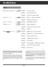
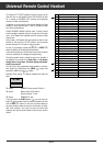
If you want to connect auxiliary units (for example, a video
recorder or decoder), your dealer can make a standard
connection by means of the following connection table:
Pin Signal TV Decoder VCR
1 = Audio output, right x x x
2 = Audio input, right x x
3 = Audio output, left x x x
4 = Audio, earth x x x
5 = Blue, earth x x
6 = Audio input, left x x
7 = RGB, blue O I
8 = Switching voltage O I I
9 = Green, earth x x
10 = –
11 = RGB, green O I
12 = –
13 = Red, earth x x
14 = Earth x x x
15 = RGB, red O I
16 = RGB, switching voltage O I
17 = Video, earth x x x
18 = RGB, switching voltage earth x x
19 = Video output x x
1)
x
20 = Video input x x
21 = Screen/earth x x x
1) Assignable per programme with baseband (see chapter "Decoder" and "Norm 1...3).
O = Output
I = Input
220
21
119
✁
P
P
-
+
É
c x
| ]