


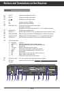
ķ
13
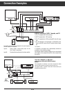
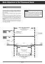
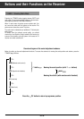
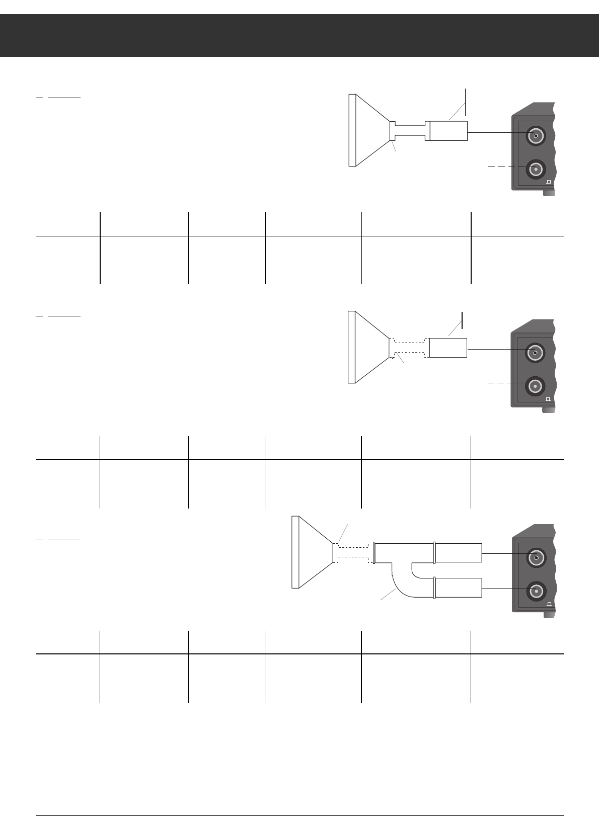
Basic Adjustment of the Polarmount Aerial
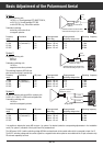
System 1
Frequency switching with
14/18 V, e.g., Grundig package STP 400/STP 300 A,
or 0/12 V, e.g., Grundig package STP 300,
or with 0/22 kHz, e.g., future Astra solution.
Polarization switching:
exclusively with motor-driven
or magnetic polarizer.
Frequency Polarization LNC power Preprogrammed Preprogrammed Switching frequency
range skew value switching voltage value
11 GHz V1 (vertical 1) 14 V approx. +30 mA 12 V 10 kHz
11 GHz H1 (horizontal 1) 14 V approx. –30 mA 12 V 10 kHz
12 GHz V2 18 V approx. +18 mA 10 V 22 kHz
12 GHZ H2 18 V approx. –18 mA 10 V 22 kHz
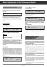
System 2
Frequency switching with
0/12 V or
0/22 kHz
Polarization switching with
14/18 V or
magnetic/motor-driven polarizer.
The switching frequency 0/22 kHz can
also be used for driving a coaxial relay.
Frequency Polarization LNC power Preprogrammed Preprogrammed Switching frequency
range skew value switching voltage value
11 GHz V1 (vertikal 1) 14 V approx. +30 mA 12 V 10 kHz
11 GHz H1 (horizontal 1) 18 V approx. –30 mA 12 V 10 kHz
12 GHz V2 14 V approx. +18 mA 10 V 22 kHz
12 GHZ H2 18 V approx. –18 mA 10 V 22 kHz
System 3
Frequency switching with input A/B for systems with
2 LNC´s (A: 11 GHz, B: 12 GHz) and waveguide filter.
Polarization switching with
14/18 V or
motor-driven/magnetic polarizer.
Frequency Polarization LNC power Preprogrammed Preprogrammed Switching frequency
range skew value switching voltage value
11 GHz V1 (vertikal 1) 14 V approx. +30 mA 12 V 10 kHz
11 GHz H1 (horizontal 1) 18 V approx. –30 mA 12 V 10 kHz
12 GHz V2 14 V approx. +18 mA 10 V 22 kHz
12 GHZ H2 18 V approx. –18 mA 10 V 22 kHz
It is possible to allocate the inputs A/B to sytem 1 or system 2 as desired (make the corresponding adjustments in the installation
menu). For system 3, allocation of the inputs A and B is predetermined.
The LNC power 14/18 V and the switching voltage 0/22 kHz are transferred via the coaxial cable which is connected to input A or B.
The 0/12 V switching voltage and the control signals for a magnetic/motor-driven polarizer are available at the 10-pole connector strip
wU
and must separately be wired.
910 . . .2050MHz
14/19V 0.5A
A
B
ON
INPUT
-
SAT
11/12
GHz
910 . . .2050MHz
14/19V 0.5A
A
B
ON
INPUT
-
SAT
11/12
GHz
910 . . .2050MHz
14/19V 0.5A
A
B
ON
INPUT
-
SAT
11 GHz
12 GHz
14/18 V
12/0 V
0/22 kHz
magnetic or motor-driven
polarizer
possible connection for second aerial
with control according to sytem 1 or 2.
12/0 V
0/22 kHz
possible connection for second aerial
with control according to sytem 1 or 2.
magnetic or motor-driven
polarizer or 14/18 V
magnetic or motor-driven
polarizer or 14/18 V
waveguide filter