


5 - 20
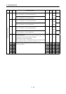
5. PARAMETERS
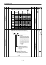
Class No. Symbol Name and function
Initial
value
Unit
Setting
range
Control
mode
50 For manufacturer setting
Must not be changed.
0000
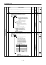
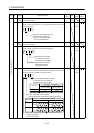
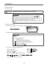
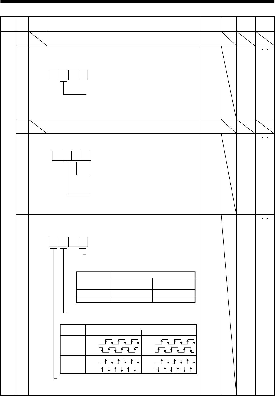
51 *OP6 Function selection 6
Used to select the operation to be performed when the alarm reset
signal switches on.
0 00
Operation to be performed when the
alarm reset signal switches on
0: Base circuit not switched off
1: Base circuit switched off
0000 0000h
to
0100h
P
S T
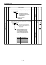
52 For manufacturer setting
Must not be changed.
0000
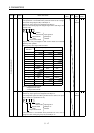
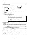
53 *OP8 Function selection 8
Used to select the protocol of serial communication.
0 0
Protocol checksum selection
0: Yes (checksum added)
1: No (checksum not added)
Protocol checksum selection
0: With station numbers
1: No station numbers
0000 0000h
to
0110h
P
S T
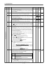
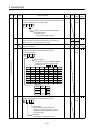
Expansion parameters 2
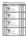
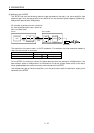
54 *OP9 Function selection 9
Use to select the command pulse rotation direction, encoder output
pulse direction and encoder pulse output setting.
0
0
1
CCW
CW
CW
CCW
Servo motor rotation direction changing
Changes the servo motor rotation
direction for the input pulse train.
Set value
Servo motor rotation direction
At forward rotation
pulse input (Note)
At reverse rotation
pulse input (Note)
Note. Refer to Section 3.4.1, (1), (a).
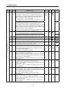
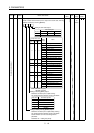
Encoder output pulse phase changing
Changes the phases of A, B-phase encoder output pulses.
Encoder pulse output setting selection (refer to parameter No. 27)
0: Output pulse setting
1: Division ratio setting
Servo motor rotation direction
Set value
CCW CW
0
1
A phase
B phase
A phase
B phase
A phase
B phase
A phase
B phase
0000 0000h
to
1101h
P
S T