5 - 2
5. PARAMETERS
5.1.2 Lists
POINT
For any parameter whose symbol is preceded by *, set the parameter
value and switch power off once, then switch it on again to make that
parameter setting valid.
For details of the parameters, refer to the corresponding items.
The symbols in the control mode column of the table indicate the following
modes:
P : Position control mode
S : Speed control mode
T : Torque control mode
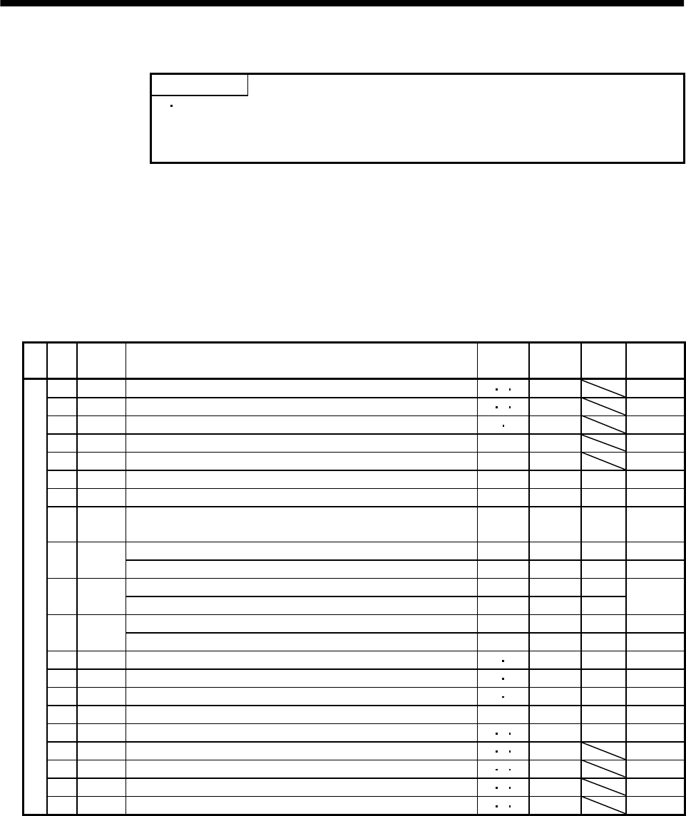
(1) Item list
No. Symbol Name
Control
mode
Initial
value
Unit
Customer
setting
0 *STY Control mode ,regenerative brake option selection P S T 0000
1 *OP1 Function selection 1 P S T 0002
2 ATU Auto tuning P S 0105
3 CMX Electronic gear numerator P 1
4 CDV Electronic gear denominator P 1
5 INP In-position range P 100 pulse
6 PG1 Position loop gain 1 P 35 rad/s
7PST
Position command acceleration/deceleration time constant
(Smoothing)
P3ms
Internal speed command 1 S 100 r/min
8SC1
Internal speed limit 1 T 100 r/min
Internal speed command 2 S 500 r/min
9SC2
Internal speed limit 2 T 500 r/min
Internal speed command 3 S 1000 r/min
10 SC3
Internal speed limit 3 T 1000 r/min
11 STA Acceleration time constant S T0ms
12 STB Deceleration time constant S T0ms
13 STC S-pattern acceleration/deceleration time constant S T0ms
14 TQC Torque command time constant T 0 ms
15 *SNO Station number setting P S T0station
16 *BPS Communication baudrate selection, alarm history clear P S T 0000
17 MOD Analog monitor output P S T 0100
18 *DMD Status display selection P S T 0000
Basic parameters
19 *BLK Parameter block P S T 0000


