


8 - 7
8. SPECIAL ADJUSTMENT FUNCTIONS
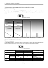
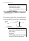
(1) Parameters No. 6, 34 to 38
These parameters are the same as in ordinary manual adjustment. Gain changing allows the values of
GD2, PG2, VG2 and VIC to be changed.
(2) Ratio of load inertia moment to servo motor inertia moment 2 (GD2B: parameter No. 61)
Set the ratio of load inertia moment to servo motor inertia moment after changing. If the load inertia
moment ratio does not change, set it to the same value as GD2 (parameter No. 34).
(3) Position control gain 2 changing ratio (PG2B: parameter No. 62), speed control gain 2 changing ratio
(VG2B: parameter No. 63), speed integral compensation changing ratio (VICB: parameter No. 64)
Set the values of after-changing position control gain 2, speed control gain 2 and speed integral
compensation in ratio (%). 100% setting means no gain change.
For example, at the setting of PG2
100, VG2 2000, VIC
20 and PG2B
180%, VG2B
150% and
VICB
80%, the after-changing values are as follows:
Position control gain 2
PG2
PG2B/100
180rad/s
Speed control gain 2
VG2
VG2B/100
3000rad/s
Speed integral compensation
VIC VICB/100
16ms
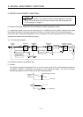
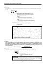
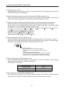
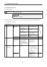
(4) Gain changing selection (CDP: parameter No. 65)
Used to set the gain changing condition. Choose the changing condition in the first digit. If you set "1"
here, you can use the gain changing (CDP) external input signal for gain changing. The gain changing
(CDP) signal can be assigned to the pins using parameters No. 43 to 48.
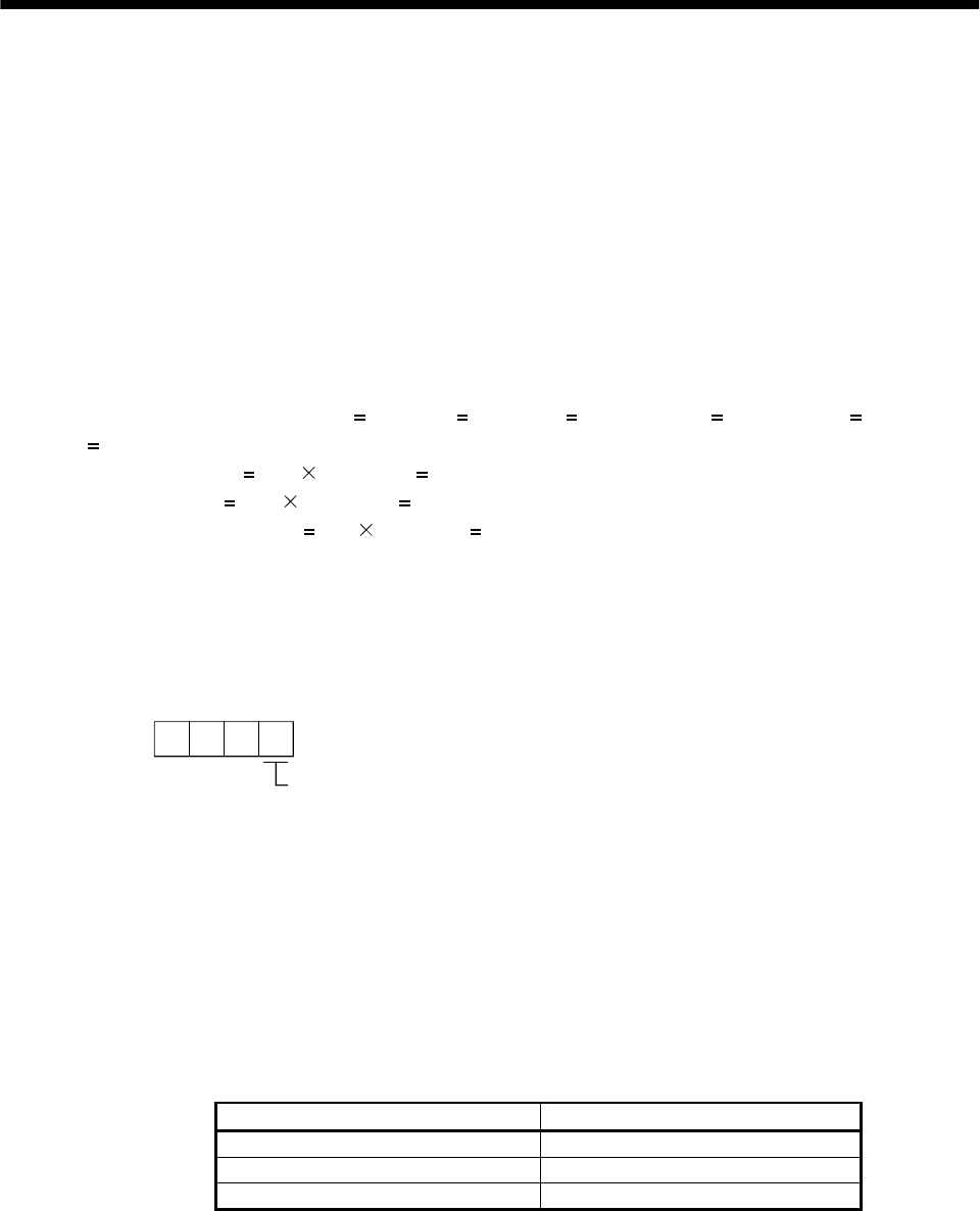
000
Parameter No. 65
Gain changing selection
Gains are changed in accordance with the settings of
parameters No. 61 to 64 under any of the following conditions:
0: Invalid
1: Gain changing (CDP) input signal is ON
2: Command frequency is equal to higher than parameter No. 66 setting
3: Droop pulse value is equal to higher than parameter No. 66 setting
4: Servo motor speed is equal to higher than parameter No. 66 setting
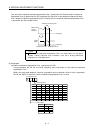
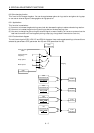
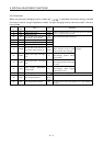
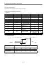
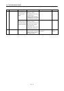
(5) Gain changing condition (CDS: parameter No. 66)
When you selected "command frequency", "droop pulses" or "servo motor speed" in gain changing
selection (parameter No.65), set the gain changing level.
The setting unit is as follows:
Gain changing condition Unit
Command frequency kpulse/s
Droop pulses pulse
Servo motor speed r/min
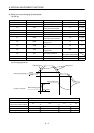
(6) Gain changing time constant (CDT: parameter No. 67)
You can set the primary delay filter to each gain at gain changing. This parameter is used to suppress
shock given to the machine if the gain difference is large at gain changing, for example.