


5
14.12.8 Output signal pin ON/OFF (DO forced output)......................................................................14-24
14.12.9 Alarm history .............................................................................................................................14-25
14.12.10 Current alarm..........................................................................................................................14-26
14.12.11 Other commands......................................................................................................................14-27
15. ABSOLUTE POSITION DETECTION SYSTEM 15- 1 to 15- 66
15.1 Outline.................................................................................................................................................. 15- 1
15.1.1 Features.........................................................................................................................................15- 1
15.1.2 Restrictions.................................................................................................................................... 15- 1
15.2 Specifications ....................................................................................................................................... 15- 2
15.3 Battery installation procedure ...........................................................................................................15- 3
15.4 Standard connection diagram ............................................................................................................ 15- 4
15.5 Signal explanation............................................................................................................................... 15- 5
15.6 Startup procedure................................................................................................................................15- 6
15.7 Absolute position data transfer protocol ...........................................................................................15- 7
15.7.1 Data transfer procedure...............................................................................................................15- 7
15.7.2 Transfer method ...........................................................................................................................15- 8
15.7.3 Home position setting..................................................................................................................15-17
15.7.4 Use of servo motor with electromagnetic brake .......................................................................15-19
15.7.5 How to process the absolute position data at detection of stroke end....................................15-20
15.8 Examples of use ..................................................................................................................................15-21
15.8.1 MELSEC-A1S (A1SD71).............................................................................................................15-21
15.8.2 MELSEC FX
(2N)
-32MT (FX
(2N)
-1PG)........................................................................................15-35
15.8.3 MELSEC A1SD75(AD75) ...........................................................................................................15-48
15.9 Confirmation of absolute position detection data............................................................................15-63
15.10 Absolute position data transfer errors ...........................................................................................15-64
15.10.1 Corrective actions ...................................................................................................................... 15-64
15.10.2 Error resetting conditions......................................................................................................... 15-66
Appendix App- 1 to App- 4
App 1. Signal arrangement recording sheets......................................................................................... App- 1
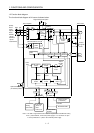
App 2. Analog monitor block diagram .................................................................................................... App- 2
App 3. Status display block diagram ...................................................................................................... App- 3