


13 - 3
13. OPTIONS AND AUXILIARY EQUIPMENT
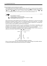
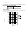
Subtract the capacitor charging from the result of multiplying the sum total of regenerative energies by
the inverse efficiency to calculate the energy consumed by the regenerative brake option.
ER [J]
Es Ec
Calculate the power consumption of the regenerative brake option on the basis of single-cycle operation
period tf [s] to select the necessary regenerative brake option.
PR [W]
ER/tf............................................................................................(13.1)
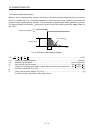
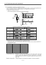
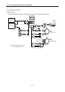
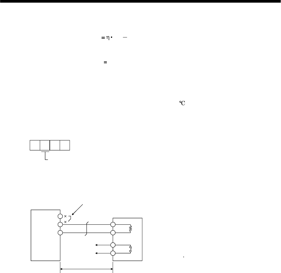
(3) Connection of the regenerative brake option
When using the regenerative brake option, always remove wiring from across P-D and install the
regenerative brake option across P-C. Set parameter No.0 according to the option to be used. The
regenerative brake option will generate heat of about 100
. Fully examine heat dissipation,
installation position, used cables, etc. before installing the option. For wiring, use flame-resistant
cables and keep them clear of the regenerative brake option body. Always use twisted cables of max.
5m length for connection with the servo amplifier.
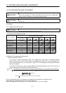
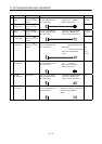
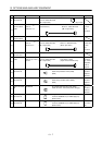
Parameter No.0
Selection of regenerative
0: Not used.
2: MR-RB032
3: MR-RB12
4: MR-RB32
5: MR-RB30
6: MR-RB50
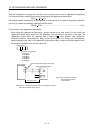
Servo amplifier
Regenerative brake option
Note: Make up a sequence which will switch off the magnetic contactor
(MC) when abnormal heating occurs.
(Note)
5m (16.4 ft) max.
G3 G4: Thermal protector terminals.
Abnormal heating will dis-
connect G3-G4.
D
P
P
C
G3
G4
C
Always remove the lead from across P-D.