


3 - 46
3. SIGNALS AND WIRING
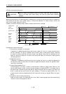
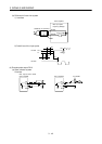
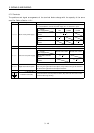
3.7.2 Terminals
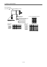
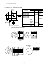
The positions and signal arrangements of the terminal blocks change with the capacity of the servo
amplifier. Refer to Section 11.2.1.
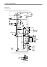
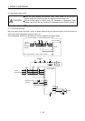
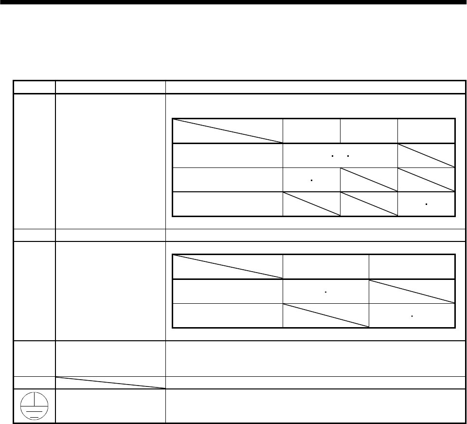
Symbol Signal Description
Supply L
1
, L
2
and L
3
with the following power:
For 1-phase 230VAC, connect the power supply to L
1
/L
2
and leave L
3
open.
Servo amplifier
Power supply
MR-J2S-10A to
70A
MR-J2S-100A
to 350A
MR-J2S-10A1
to 40A1
3-phase 200 to 230VAC,
50/60Hz
L
1
L
2
L
3
1-phase 230VAC,
50/60Hz
L
1
L
2
1-phase 100 to 120VAC,
50/60Hz
L
1
L
2
L
1
, L
2
, L
3
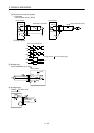
Main circuit power supply
U, V, W Servo motor output Connect to the servo motor power supply terminals (U, V, W).
Servo amplifier
Power supply
MR-J2S-10A to 350A MR-J2S-10A1 to 40A1
1-phase 200 to 230VAC,
50/60Hz
L
11
L
21
1-phase 100 to 120VAC,
50/60Hz
L
11
L
21
L
11
, L
21
Control circuit power supply
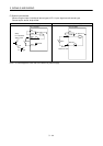
P, C, D Regenerative brake option
P and D are factory-connected.
When using the regenerative brake option, always remove wiring from across P-D
and connect the regenerative brake option across P-C.
N Do not connect.
Protective earth (PE)
Connect this terminal to the protective earth (PE) terminals of the servo motor
and control box for grounding.