6 - 10
6. DISPLAY AND OPERATION
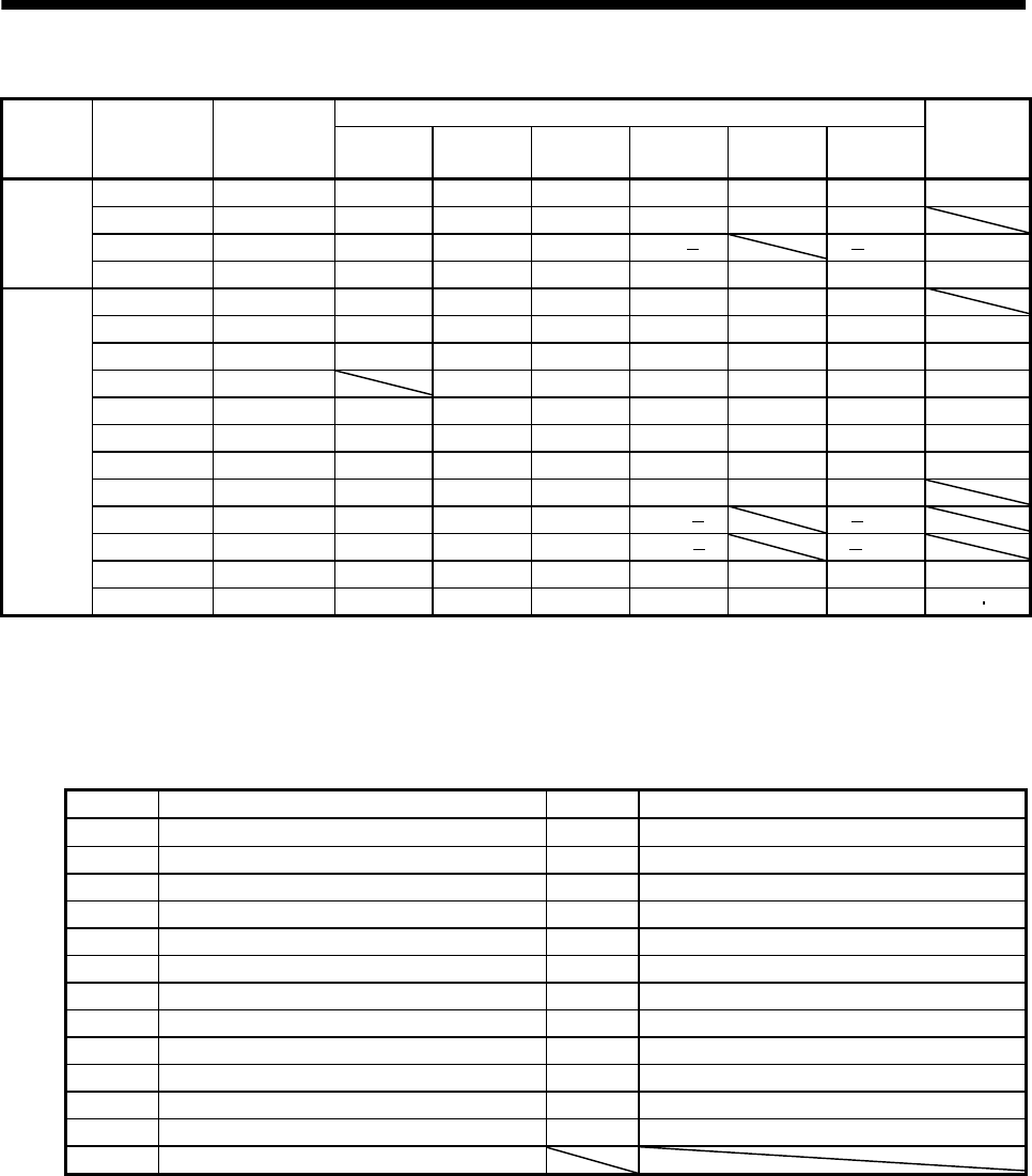
(a) Control modes and I/O signals
(Note 2) Symbols of I/O signals in control modes
Connector Pin No.
Signal
input/output
(Note 1) I/O
P P/S S S/T T T/P
Related
parameter
8 I CR CR/SP1 SP1 SP1 SP1 SP1/CR No.43 to 48
14O OPOPOPOPOPOP
18 O INP INP/SA SA SA/ /INP No.49
CN1A
19O RDRDRDRDRDRDNo.49
(Note 3) 4 O DO1 DO1 DO1 DO1 DO1 DO1
5 I SON SON SON SON SON SON No.43 to 48
6 O TLC TLC TLC TLC/VLC VLC VLC/TLC No.49
7 I LOP SP2 LOP SP2 LOP No.43 to 48
8 I PC PC/ST1 ST1 ST1/RS2 RS2 RS2/PC No.43 to 48
9 I TL TL/ST2 ST2 ST2/RS1 RS1 RS1/TL No.43 to 48
14 I RES RES RES RES RES RES No.43 to 48
15 I EMG EMG EMG EMG EMG EMG
16 I LSP LSP LSP LSP/ /LSP
17 I LSN LSN LSN LSN/ /LSN
18 O ALM ALM ALM ALM ALM ALM No.49
CN1B
19 O ZSP ZSP ZSP ZSP ZSP ZSP No.1
49
Note: 1. I: Input signal, O: Output signal
2. P: Position control mode, S: Speed control mode, T: Torque control mode, P/S: Position/speed control change mode, S/T:
Speed/torque control change mode, T/P: Torque/position control change mode
3. The signal of CN1A-18 is always output.
(b) Symbol and signal names
Symbol Signal name Symbol Signal name
SON Servo-on EMG Emergency stop
LSP Forward rotation stroke end LOP Control change
LSN Reverse rotation stroke end TLC Limiting torque
CR Clear VLC Limiting speed
SP1 Speed selection 1 RD Ready
SP2 Speed selection 2 ZSP Zero speed
PC Proportion control INP In position
ST1 Forward rotation start SA Speed reached
ST2 Reverse rotation start ALM Trouble
RS1 Forward rotation selection WNG Warning
RS2 Reverse rotation selection OP Encoder Z-phase pulse (open collector)
TL Torque limit BWNG Battery warning
RES Reset


