


3 - 39
3. SIGNALS AND WIRING
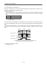
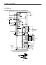
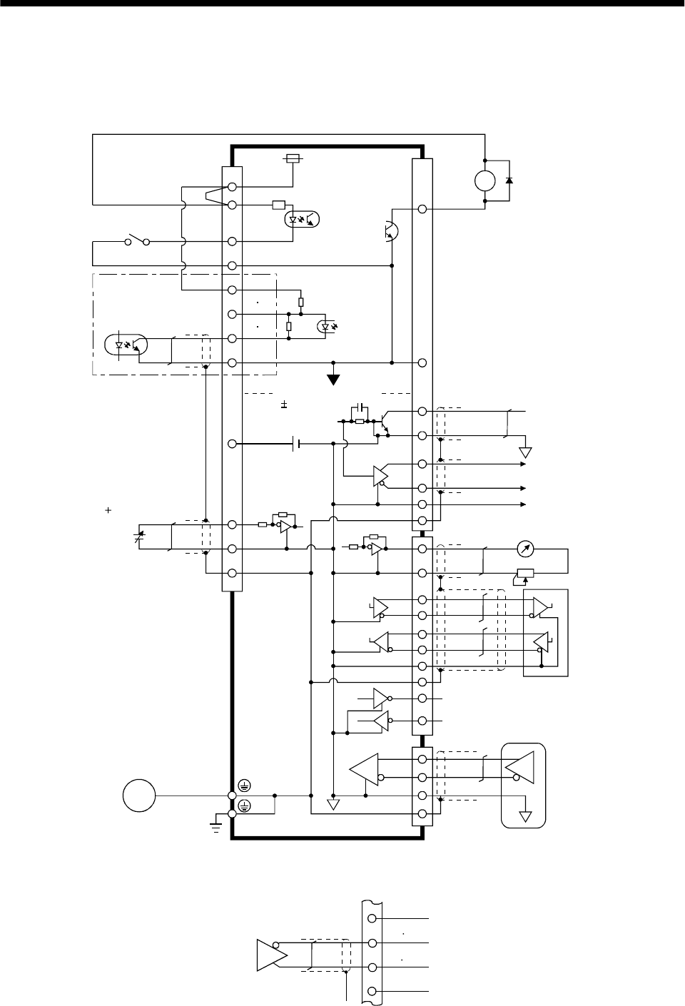
3.6 Interfaces
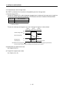
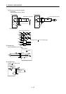
3.6.1 Common line
The following diagram shows the power supply and its common line.
DC24V
CN1A
CN1B
CN1A
CN1B
DO-1
SG
OPC
PG NG
SG
P15R
LG
TLA
VC etc.
SD
OP
MR
MRR
SM
DI-1
COM
VDD
ALM .etc
LG
SD
RDP
RDN
SDP
SDN
LG
CN3
RA
CN2
SD
MO1
MO2
LG
SG
TXD
RXD
RS-232C
RS-422
(Note)
Analog input
( 10V/max. current)
Servo motor
Ground
SD
LG
Servo motor encoder
Isolated
15VDC 10%
30mA
LA etc.
Monitor analog output
SON, etc.
PP NP
LG
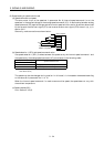
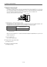
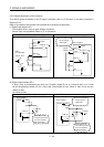
Note: For the open collection pulse train input. Make the following
connection for the different line driver
p
ulse train in
p
ut.
Differential line
driver output
35mA max.
LAR
etc.
SG
PP
NP
PG
NG
OPC