


03
32
En
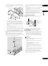
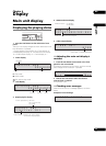
2 Attach the HDMI retaining cover to the HDMI
cable.
Mount the HDMI retaining cover so that it retains the
connector securely.
• Depending on the HDMI cable’s connector size, the
gap and positional relationship between the HDMI
retaining cover and HDMI holder may differ.
3 Tighten the HDMI retaining cover’s screw into
the HDMI screw hole to fasten the HDMI cable to this
unit.
Caution
• Do not tighten the screw with excessive force. Doing
so could damage the connector or cable.
•If the HDMI retaining cover is damaged, do not
continue using it. The cable could come loose or the
terminal could be damaged.
• The HDMI retaining cover is only designed to retain
the connector. This does not provide strength against
loads applied when the cable is pulled on, so be sure
to fasten the cable to the rack, etc.
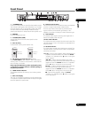
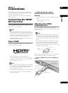
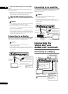
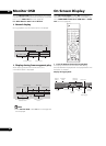
Connecting to a display
When also connecting to an amplifier using the HDMI
cable, see Connecting to an amplifier (below).
Caution
• Hold the connector when connecting and
disconnecting cables.
• Applying excessive force to the connector could
result in faulty contact and prevent video signals from
being output.
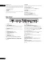
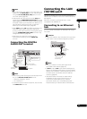
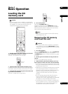
Connecting to an amplifier
For instructions on connecting the amplifier and display
or the amplifier and speakers, see the amplifier’s
operating instructions.
Caution
• Hold the connector when connecting and
disconnecting cables.
• Applying excessive force to the connector could
result in faulty contact and prevent video signals from
being output.
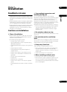
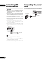
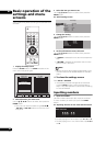
Connecting the
VIDEO OUT and
AUDIO OUT terminals
Connecting to a display
LAN(10/100)
EXT SYNC IN
ON
75
OFF
NTSC
C
R / PRCB / PBY
TV
SYSTEM
PAL
VIDEO OUT
COMPONENT
VIDEO OUT
HDMI
OUT
DIGITAL
AU DIO
OUT
AU DIO
OUT
L
R
Rear panel
To HDMI
input
Display
Direction of
signal flow
Match the direction
of the plug to the
terminal and insert
the plug straight in.
It is also possible to connect this
unit to an amplifier using the
HDMI cable. (See below)
HDMI cable
(commercially
available)
LAN(10/100)
EXT SYNC IN
ON
75
OFF
NTSC
C
R / PRCB / PBY
TV
SYSTEM
PAL
VIDEO OUT
COMPONENT
VIDEO OUT
HDMI
OUT
DIGITAL
AU DIO
OUT
AU DIO
OUT
L
R
Rear panel
To HDMI
input
terminal
Display
Direction of signal flow
Match the direction
of the plug to the
terminal and insert
the plug straight in.
HDMI cable
(commercially
available)
HDMI cable
(commercially
available)
Amplifier
From HDMI
output
terminal
To HDMI input
terminal
EXT SYNC IN
ON
75
OFF
NTSC
C
R / PRCB / PBY
TV
SYSTEM
PAL
VIDEO OUT
COMPONENT
VIDEO OUT
HDMI
OUT
DIGITAL
AU DIO
OUT
AU DIO
OUT
R
S-232C
L
R
Rear panel
It is also possible to connect
to an amplifier. Use an audio
cable (2-channel) or coaxial
digital audio cable to
connect (see page 33).
Audio cable
(commercially available)
BNC cable
(commercially
available)
To audio input terminal
To video input terminal
To component
video input
terminals
Direction of signal flow
Display
Connect the VIDEO
OUT terminal or
COMPONENT VIDEO
OUT terminals. Use a
BNC cable with a
characteristic
impedance of 75 Ω.