


09
64
En
Chapter 9
Communications/Control
About the
Communications
Interface User’s
Manual
For detailed information on the serial/LAN interface
commands, download the “HD-V9000 Communications
Interface User’s Manual” from the Pioneer website.
Serial interface
specifications
This unit is equipped with a serial control interface
conforming to RS-232C standards, allowing it to be
connected to a computer with either a 9-pin or a 15-pin
D-Sub connector. The connector to be used can be
switched at Initial Settings Options Serial Port
(page 47).
Caution
• It is not possible to access the 9-pin and 15-pin
connectors simultaneously.
• Both the 9-pin connector and the 15-pin connector
use inch screw threads.
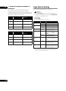
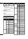
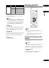
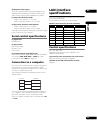
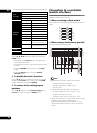
The connectors’ pin layouts are as shown below.
15-pin D-Sub connector
9-pin D-Sub connector
Control functions
(a) Serial control
TxD, RxD and DTR
Serial control interface conforming to RS-232C
standards.
(b) Extend terminals
SW1, SW2, SW3, SW4, SW5, SW6, SW7 and SW8
This unit can be controlled by connecting switches to the
exterior of these pins.
(c) External power supply control
This unit’s power can be turned on and off using the
interface connector’s power pin.
Power off control is not possible when operation of the
buttons on the main unit’s front panel or remote control
unit is locked.
• When power is off (in the standby mode): Power
turns on when L signal detected after H signal of
100 msec or greater
• When power is on: Power turns off (to the standby
mode) when L signal detected after H signal of
100 msec or greater
Pin input voltage: ±12 V or less; H signal level: 4.5 V or
higher, L signal level: 0.5 V or lower
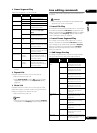
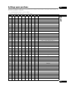
Pin no. Pin name Input/
Output
Function
1GND-- ground
2 TxD Output send data
3 RxD Input receive data
4 DTR Output enable data receiving
5 POWER Input external power control
6 SW1 Input Extend Terminal
7 SW2 Input Extend Terminal
8 SW3 Input Extend Terminal
9 SW4 Input Extend Terminal
10 SW5 Input Extend Terminal
11 SW6 Input Extend Terminal
12 SW7 Input Extend Terminal
13 SW8 Input Extend Terminal
14 NC -- NC (not connected on
this unit)
15 STOP_ST Output Stop/Play Status
51
6
9
1
915
8
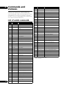
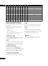
Pin no. Pin name Input/
Output
Function
1 DCD Input NC (not connected on
this unit)
2 RxD Input receive data
3 TxD Output send data
4 DTR Output enable data receiving
5GND-- Ground
6 DSR Input NC (not connected on
this unit)
7 RTS Output Connected internally to
CTS
8 CTS Input Connected internally to
RTS
9 RI Input NC (not connected on
this unit)