


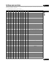

65
En
09
English
(d) Playback status output
This unit’s operating status (playing/stopped) can be
detected with the interface connector’s STOP_ST pin.
There are two output modes, settable by command.
(1) Stop status detection mode
When in stop mode “L” is output
When in any other mode “H” is output
(2) Play status detection mode (default)
When in play mode “L” is output
When in any other mode “H” is output
The output is of the open collector type, so pull the voltage
up to a maximum of 12 V (50 mA).
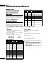
Serial control specifications
(1) Signal level
RS-232C level
(2) Data format
Data length: 8 bits
Stop bits: 1 bit
Parity: None
(3) Communications speed (baud rate)
The communications speed (baud rate) can be selected
from among 2400, 4800, 9600 or 19200 bps. Upon
purchase it is set to 9600 bps (page 47).
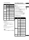
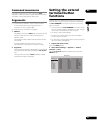
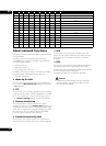
Connection to a computer
This unit communicates with the computer using pins 2
and 3 of the 9- or 15-pin D-Sub connector for signal
transfer. Pin 5 of the 9-pin connector or pin 1 of the 15-pin
connector is used as the ground.
The computer and set are connected as shown on the
diagram below.
This unit can accept commands whenever the power is
on. In addition, it can receive the Power On command
even when the power is off (in the standby mode).
There is no need to connect control lines other than TxD
and RxD.
LAN interface
specifications
This unit is equipped with a LAN terminal. It can also be
controlled via LAN cable.
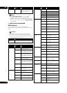
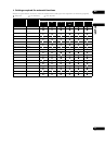
The connector’s pin layout is as shown below.
Modular jack (conforming to RJ-45 standards)
Control specifications
TD+, TD–, RD+, RD–
Ethernet interface conforming to 10BASE-T and
100BASE-TX standards.
(1) Control by same commands as for serial control
See Commands and statuses on page 66.
(2) Wake Up On LAN (remote power control)
(page 70)
Computer HD-V9000
TxD RxD
RxD TxD
GND GND
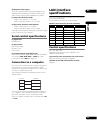
Pin No. Pin Name Input/Output Function
1 TD+ Output LAN line TX+
2 TD– Output LAN line TX–
3 RD+ Input LAN line RX+
4NC
5NC
6 RD– Input LAN line RX–
7NC
8NC