Operating Instructions
Operating Notes
2
2-5
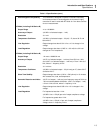
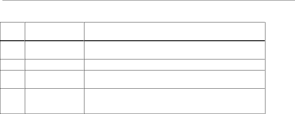
Table 2-1. Controls, Indicators, and Connectors (cont.)
Ref.
No Name Function
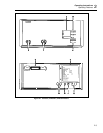
8 Power Connector Provides the means of connecting the 5220A to ac line power by way of
a 3-wire power cord.
9 Fuse Holder Houses the ac line fuse and allows easy access for fuse replacement.
10 Ground Connector A binding post positioned to provide a convenient connection to chassis
ground.
11 Current Output
Terminals (Rear)
A pair of banana-jack terminals used as rear-panel current output
connections. The terminals are inactive when the front-panel CURRENT
OUTPUT terminals are selected.
2-9. Operating Notes
The following paragraphs describe the various conditions that should be considered
before operating the 5220A.
2-10. AC Line Connection
The rear-panel three-prong, U-ground connector permits the 5220A to be connected,
through a power cord to 50 or 60 Hz line power. The offset prong on this connector is
connected to the 5220A chassis and should be connected, via the power cord, to a high-
quality earth ground.
2-11. Transconductance Amplifier
A transconductance amplifier is a current source whose output current level is
proportional to an analog input voltage. Electrically, the output of the unit appears as a
constant current source with an output impedance that is much greater than the load
resistance. Similarly, its input impedance is much greater than that of the input voltage
source.
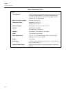
The input/output ratio of the 5220A is 1:1, and the output current range is +20 to –20 A.
Therefore, the range of the input control voltage is +20 to –20 V dc. The compliance
voltage of the 5220A is 3 V rms ac or +4 V dc.
2-12. Input Voltage Requirements
Input control voltage for the 5220A can be supplied by any low-impedance voltage
source with an output proportional to the desired output current. The source may be either
ac (30 Hz to 1 kHz) or dc, fixed or adjustable, depending upon the output requirements.
The control voltage source may be connected to either the front-panel VOLTAGE
INPUT terminals or the rear-panel voltage input terminals (Pins 5 (low) and 6 (high) of
the 24-pin connector), but not both simultaneously. Instrument damage will not result
from the simultaneous connection of two sources. However, interaction between the two
inputs can result in source loading, which in turn can cause inaccuracy in the expected
current output level.
If a rear-panel input is desirable, the use of the 5100 Series Calibrator and a Y5000
Interface is recommended. This combination allows the 5220A to be operated remotely
as an extension of the 5100. If the use of an alternate rear-input source is desirable, the
user is responsible for the proper interface. Details for custom interface requirements can
be derived from the theory of operation (Section 3) and the detailed schematics (Section
8).


