5 220A
Instruction Manual
3-14
The shift-right mode is selected when flop-flop U17-1 responds to an operate command
(D-input low) and drives the register’s S0 input high and the S1 input low. This results in
the high input at U22-2 being sequentially propagated through the register and its four
outputs (QD, QC, QB and QA) being driven high (operate).
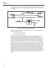
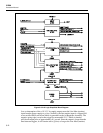
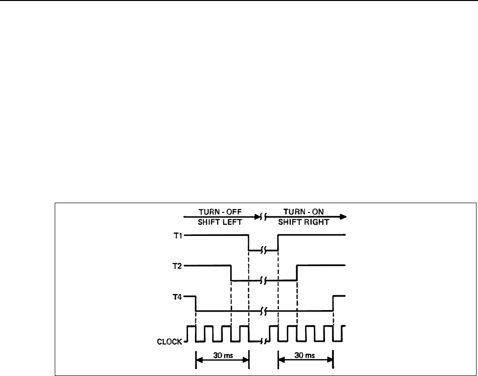
The outputs of the shift register are used as control signals to sequence the turn-on and
turn-off of the transconductance amplifier. They are designated T1, T2, and T4 (T3 is not
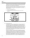
used) and their sequence is shown in Figure 3-9. The control function of each of the
signals is as follows:
1. T1 turns the A6 Driver on and off.
2. T2 turns the A5 Preamplifier on and off.
3. T4 enables/disables the selected front/rear input relay (K1 or K2) on the A5
preamplifier.
ajs14f.wmf
Figure 3-9. Timing Sequence
3-16. Standby/Operate Logic
The standby/operate logic consists of optical isolators U1 and U5, monostable U8-7, D-
type flip-flop U10-9, and a series of supporting logic gates and buffers. Its function is
twofold. One, it responds to reset and external inputs to command the state of the timing
logic, shift left (standby mode) or shift right (operate). Two, it drives the front-panel
STANDBY/OPERATE LEDs and provides the A11 MIS Bus Interface (remote interface)
with an Interface Operate Status (Standby/Operate) signal. Flip-flop U10-9 is used to
store the commanded mode (standby or operate) and to provide the necessary commands
to the shift register (in the timing logic) and the LED/status drivers. Optical isolators U1
and U5 are used to electrically isolate remote control signals to and from the A11 MIS
Bus Interface from the A10 Logic.
Standby/operate commands occur in the form of Reset, Standby/Operate, not Operate,
Sw(itch) 1, Overcompliance, and Overcurrent. Reset is an onboard command from the
reset logic. It sets the 5220A to standby by commanding U10-9 to the clear state (Q low).
Standby/Operate is received in the form of a +5 V (high) input each time the front-panel
STANDBY/OPERATE switch is pressed. If the 5220A is in the local control mode, each
press of the switch will clock flip-flop U10-9 to its alternate state. The result is an
alternate selection of either the standby or the operate mode, as indicated by the front-
panel STANDBY and OPERATE LEDs. A similar command, Interface Operate Status
(also derived from the state of U10-9), is issued to the A11 MIS Bus Interface; low


