5 220A
Instruction Manual
3-4
3-5. Digital Section
The logic portion of the 5220A controls the sequencing of input relays (front/rear) and
other control signals that turn the transconductance amplifier on and off. It also provides
drive commands to light appropriate front panel status LEDs. Inputs to the logic are in the
form of local/remote control commands from the front panel switches or the remote MIS
Bus Interface, and overload signals from the analog control circuit.
Local or front panel control of the 5220A is accomplished through a series of front panel
pushbutton switches which provide direct inputs to the logic circuit. Control and/or status
responses to the commands are displayed on the front panel LEDs.
Remote control of the 5220A is enabled by the A11 MIS Bus Interface. The interface is
intended for use with a 5100 Series Calibrator equipped with a Y5000 Interface. Control
data (analog and digital) is received at the A11 MIS Bus Interface by way of a connector
on the rear panel of the 5220A. In the remote mode, this data is processed by the interface
and internally coupled with the analog and digital sections of the 5220A.
3-6. Circuit Analysis
A detailed circuit description of the 5220A is given in the following paragraphs. The
description is keyed to the functional blocks defined in Figure 3-1. Each block is
described separately and is supported by both a block diagram and a detailed schematic
diagram (see Section 8 for schematics).
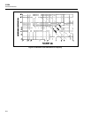
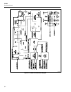
3-7. Power Supply
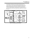
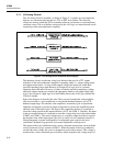
The power supply, as shown in Figure 3-3, consists of the three major assemblies: A2
Transformer, A3 Cap Bus, and A4 Regulator. Its function is to transform line power into
four sets of 5220A operating voltages. Each voltage set is isolated from the other, and
three of the four are regulated. The three regulated voltage sets are +15/-15 V dc,
+5 V dc, and +5 V ISO (isolated). The unregulated voltage set is +12/-12 V dc.
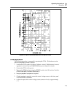
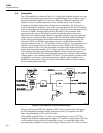
The A2 Transformer assembly consists of a series of three line-voltage selection
switches, a power transformer, and appropriate secondary output fuses. Line power to the
transformer passes through the front panel power switch (S4) and the line voltage
selection switches before reaching the two primary windings. The setting of the line
voltage switches (S1) connects the primary windings in either a parallel or a series
configuration. Parallel connection is required for 115 V ac operation and the series
connection is used for 230 V ac. Switches S2 and S3 allow selection of alternate primary
winding taps. They allow operation from 100, 110, 115 or 120 V ac line voltages in the
parallel configuration, or from 200, 220, 230 or 240 V ac in the series configuration. The
115 V ac ventilation fan is permanently connected to one of the primary windings, thus
ensuring proper operation in either voltage configuration. Fuse protection for the power
line is provided by an external fuse (F1) mounted on the rear panel. Supply overload
protection for the regulated supplies is provided by secondary-winding fuses F4, F5, F6,
and F7 located on the A2 Transformer Assembly.
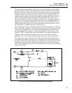
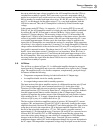
The A3 Cap Bus is a high-current, unregulated, +12/-12 V dc power supply designed to
provide operating power to the output amplifier. It consists of two fuses, a full-wave
rectifier, two bleeder resistors, and a bank of filter capacitors. Operating voltage is
derived from a high-current center-tapped secondary winding of T1. It enters the A3 Cap
Bus through overload fuses F2 and F3, and is full-wave rectified by diodes CR1 through
CR4 to establish both positive and negative supply voltages. Filter capacitors, C1 through
C8, filter the supply outputs. Bleeder resistors, R2 and R3, discharge the filter capacitors
when line power is turned off.


