Maintenance
Troubleshooting
4
4-25
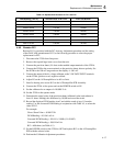
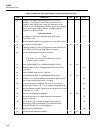
Table 4-7. Analog Section Troubleshooting Guide
Step Instruction Yes No Go to
1 Complete the troubleshooting procedure given in Table 4-6. 2
2 Set the 5220A POWER switch to OFF. 3
3 Connect a jumper wire between the front panel VOLTAGE
INPUT terminals.
4
4 Connect a 0.1 Ω resistor between the selected output terminals,
then connect a DVM across the 0.1 Ω resistor.
5
5 Set the POWER switch to ON and select the operate mode. 6
6 Does the 5220A remain in the operate mode? 8 9
7 If the 5220A trips to standby and indicates an overcompliance or
overcurrent condition, the A5 Preamplifier PCB is at fault. Check
voltage levels on the active components on the A5 preamplifier
PCB while the unit is in standby. Repair as required.
8
8 Using a tuning tool, adjust R1, Zero Adjust, on the A5
Preamplifier PCB for a DVM reading of 0 V ±3 µV dc. The
adjustment should cover a range or 0 V ±5 µV.
9
9 Can R6 be adjusted for a DVM reading or 0 V ±3 µV? 17 10
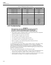
10 Connect the DVM from TP4 (high) to TP5 (low) on the A5
Preamplifier PCB Assembly. With the 5220A in the operate
mode the DVM should read –15 V dc.
11
11 Does the DVM read –15 V dc? 13 14
12 Troubleshoot the Turn on 1 circuit starting with the level-shifting
transistors Q3 and Q4 on the A8 Analog Control PCB Assembly.
Then check for a T1 output from U22 on the A10 Logic PCB
Assembly. Repair as required.
13 Connect the DVM from TP6 (high) to TP5 (low) on the A5
Preamplifier PCB Assembly. With the 5220A in the operate
mode, the DVM should read –15 V dc.
14
14 Does the DVM read –15 V dc? 16 15
15 Troubleshoot the FET Drive 1 circuit starting with the level-
shifting transistors Q1 and Q2 on the A8 Analog Control PCB
Assembly. Then check for a T2 output from U22 on the A10
Logic PCB Assembly. Repair as required.
8
16 The A5 Preamplifier PCB Assembly is defective. Check voltage
levels on the active components on the A5 Preamplifier while the
unit is in standby. Repair as required.
8
17 The A5 Preamplifier, A6 Driver, and A7 Output stages are
operating properly. Set the 5220A to standby, remove and
replace the front panel short at the VOLTAGE INPUT terminals
with a 1.0 V dc voltage source; positive to red, negative to black.
18
18 Reconnect the DVM across the 0.1 Ω resistor to the output
terminals.
19


