Theory of Operation
Circuit Analysis
3
3-15
indicates standby, high indicates operate. The not Operate signal is received from the
A11 MIS Bus Interface and is effective only when the 5220A is in the remote control
mode. In the high state, the signal clears flip-flop U10-9 to invoke the standby mode.
When not Operate goes low it presets flip-flop U10-9 (by way of U8-7) to invoke the
operate mode. Overload signals received at the standby/operate logic include; Thermal
Sw(itch) 1, Overcompliance and Overcurrent. When any one of these signals goes high,
flip-flop u10-9 is cleared to the standby state.
3-17. Local/Remote Logic
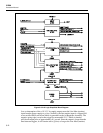
The local/remote logic consists of optical isolators U4 and U20-8, monostable U8-9,
D-type flip-flop U7, and a series of supporting logic gates and buffers. Its function is to
enable selection of the desired control mode (local or remote) and to provide the drive for
the appropriate front panel and A11 MIS Bus Interface status indicators. These include
LLO (Local Lock Out) LED, Remote LED, and Interface Remote Status. Flip-flop U7 is
used to store the commanded mode (local or remote) and to provide the necessary
commands to the onboard logic and the LED/status drivers. Optical isolators U4 and
U20-8 electrically isolate remote control signals to and from the A11 MIS Bus Interface
from the A10 Logic.
Local/remote commands are received in the form of Local, not Remote, and not LLO
(Local Lockout). Local occurs as a momentary +5 V (high) input each time the front
panel LOCAL switch is pressed. If the 5220A is in the remote control mode and Local
Lockout is not commanded (high) pressing the front panel LOCAL switch will initiate a 1
µs pulse from monostable U8-9. This pulse clears flip-flop U7, which in turn, commands
the A10 Logic to the local mode (Rem Stat low). As a result, the Remote LED and LLO
LED signals are high, Interface Remote Status is low. However, if not LLO is low when
the LOCAL switch is pressed, monostable U8-9 will be held in the reset state and flip-
flop U7 will not be cleared. Thus, the A10 Logic is effectively locked into the remote
mode until not LLO is returned high.
The not Remote signal is received from the A11 MIS Bus Interface and is used to
remotely command the A10 Logic to the remote control mode. When the signal goes low
it is coupled across optical isolator U4 to the clock input of D-type flip-flop U7. This sets
the Q Output of U7 high to select the remote control mode (Rem Stat high). As a result,
the Remote LED signal goes low to light the REMOTE LED and the Interface Remote
Status output goes high.
When the 5220A is commanded to the remote mode the front-panel
STANDBY/OPERATE and FRONT/REAR switches are disabled and the corresponding
remote inputs are enabled. Similarly, if LLO is remotely enabled, the LOCAL pushbutton
is disable.
3-18. Front/Rear Input Logic
The front/rear input logic is used to command the front/rear input relays on the A5
Preamplifier and to drive the appropriate FRONT/REAR LED on the front panel. When
the A10 Logic is in the local mode, Front/Rear commands are received from the front
panel pushbutton. Each switch depression is received as a +5 V (high) level that is used
to clock alternate states on D-type flip-flop U10-5. The FRONT LED and Relay K1 are
commanded when the Q output of U10-5 is low. When the A10 Logic is in the remote
mode the not Rear input signal is used to command the front/rear input relays. Front input
is selected when not Rear is high. Actual opening/closing of the relays is enabled at time
T4 of the timing logic.


