5 220A
Instruction Manual
2-6
2-13. Input Voltage Selection, Front/Rear
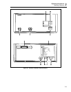
Selection of the front or rear terminals for control voltage input is manually accomplished
by pressing the INPUT push button switch on the front panel. Each depression alternately
selects front or rear as indicated by the lit FRONT/REAR LED indicator. This switch is
active in the local mode, and inactive in the remote mode.
2-14. Current Output, Front/Rear
The 5220A current output can be taken from either a front- or rear-panel set of five-way
binding post terminals, but not both simultaneously. An internal jumper configuration
allows qualified personnel to establish the desired output. A detailed output selection
procedure is given in Section 4, Maintenance.
2-15. Standby/Operate
When the 5220A is energized it can be placed into one-of-two operating modes; standby
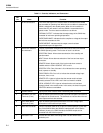
or operate. The enabled mode is indicated by a lit front panel LED; OPR (operate) or
STDBY (standby). Standby is essentially a reset state, in which the output of the
transconductance amplifier is forced to zero regardless of the input control voltage level.
In the standby mode both the amplifier and the device connected to its output are
protected from accidental overloads. The operate mode is enabled when an output is
required. It causes the amplifier to respond to the control voltage input, and thereby
provides the appropriate current level output.
A front panel pushbutton switch (located between the OPR/STDBY LEDs) allows
manual selection of either mode when the LOCAL LOCKOUT LED is not lit. However,
the selection can be counteracted under certain conditions. For example, either mode may
be remotely selected, and the detection of an output overload will command the standby
mode. Similarly, when the unit is initially energized it is forced to standby.
2-16. Local/Remote
The 5220A can be operated manually using the front panel controls, or remotely by way
of the rear panel connector. When the unit is initially energized, it is forced to the local
control mode (REMOTE LED is not lit). The remote mode can only be selected by way
of a remote control source. When remote is enabled (REMOTE LED is lit) the local
mode can be recalled by a remote command or by pressing the LOCAL push-button
switch on the front panel. However, if the LOCAL LOCKOUT is lit (this is also a remote
command) the local mode can only be recalled by a remote command.
2-17. Status Indicators
A series of three front-panel STATUS LEDs provide a visual indication of overload
conditions that have been detected at the 5220A output. They are: THERMAL CUTOFF,
OVERCOMPLIANCE, and OVERCURRENT. When any one of these conditions is
detected the appropriate LED is lit and the unit is commanded to standby. The LED will
remain lit even after the overload condition has been relieved. To return the unit to the
operate mode the overload must be cleared and the operate mode must be commanded. If
operate is commanded while the overload is still present, the unit will remain in standby.
A thermal cutoff indication identifies overheating of the current output stage. If the
heating is excessive a cooling-down period may be required before the condition is
cleared.
The presence of an open-circuit or a high impedance load at the output terminals will
cause an overcompliance indication. In this case, an appropriate load will have to be


