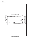
5220A
Instruction Manual
ii
3-8. Preamplifier...................................................................................... 3-6
3-9. A6 Driver ......................................................................................... 3-7
3-10. A7 Output......................................................................................... 3-9
3-11. A8 Analog Control........................................................................... 3-10
3-12. A9 Front Panel ................................................................................. 3-11
3-13. A10 Logic ........................................................................................ 3-11
3-14. Reset Logic .................................................................................. 3-11
3-15. Timing Logic ............................................................................... 3-13
3-16. Standby/Operate Logic ................................................................ 3-14
3-17. Local/Remote Logic .................................................................... 3-15
3-18. Front/Rear Input Logic ................................................................ 3-15
3-19. Failure Status Logic..................................................................... 3-16
3-20. A11 MIS Bus Interface .................................................................... 3-16
4 Maintenance....................................................................................... 4-1
4-1. Introduction .......................................................................................... 4-1
4-2. Service Information.............................................................................. 4-2
4-3. General Maintenance............................................................................ 4-2
4-4. Cleaning ........................................................................................... 4-2
4-5. Air Filter Maintenance..................................................................... 4-2
4-6. Access Information .......................................................................... 4-2
4-7. Internal Components/Assemblies ................................................ 4-4
4-8. Front Panel Removal ................................................................... 4-4
4-9. A9 Front Panel PCB Removal..................................................... 4-4
4-10. A2 Transformer Assembly Removal ........................................... 4-4
4-11. A6 Driver and A7 Output Assembly Removal............................ 4-5
4-12. A3 Cap Bus Removal .................................................................. 4-5
4-13. A12 Shunt Assembly Removal.................................................... 4-5
4-14. Fuse Replacement ............................................................................ 4-6
4-15. Ac Line Fuse................................................................................ 4-6
4-16. Power Supply Fuses..................................................................... 4-6
4-17. Line Voltage Selection..................................................................... 4-6
4-18. Output Terminal Selection, Front/Rear............................................ 4-7
4-19. Service Tools.................................................................................... 4-8
4-20. Performance Test.................................................................................. 4-8
4-21. Initial Conditions.............................................................................. 4-8
4-22. Front Panel Tests.............................................................................. 4-9
4-23. Zero Output...................................................................................... 4-9
4-24. DC Accuracy and Line Regulation .................................................. 4-10
4-25. Harmonic Distortion......................................................................... 4-10
4-26. Frequency Response......................................................................... 4-11
4-27. Overcurrent Trip Test....................................................................... 4-11
4-28. Overvoltage Trip Test ...................................................................... 4-12
4-29. Calibration Adjustments....................................................................... 4-12
4-30. Initial Conditions.............................................................................. 4-13
4-31. Input Offset Adjustment................................................................... 4-13
4-32. Driver Offset Adjustment................................................................. 4-13
4-33. Output Bias Adjustment................................................................... 4-14
4-34. DC Accuracy Adjustment ................................................................ 4-14
4-35. Frequency Response......................................................................... 4-14
4-36. Overcurrent Adjustment................................................................... 4-15
4-37. Overvoltage Adjustment .................................................................. 4-15
4-38. Replacement of Selected Components ................................................. 4-15
4-39. Resistors R11 and R12..................................................................... 4-16


