


4-1
Section 4
Maintenance
4-1. Introduction
WWarning
These servicing instructions are for use by qualified personnel
only. To avoid electric shock, do not perform any servicing
other than that contained in the operation instructions unless
you are qualified to do so.
This section of the manual contains maintenance information for the Model 5220A
Transconductance Amplifier. The material is presented under the categories of shipping
information, general maintenance, performance test, calibration adjustments, and
troubleshooting. The performance test is recommended as an acceptance test when the
unit is first received, and later as a calibration procedure to verify the 180-day
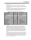
specifications. Table 4-1 lists the equipment required for both the performance test and
calibration adjustments. If a recommended model is not available, an equivalent
instrument meeting the required characteristics can be substituted.
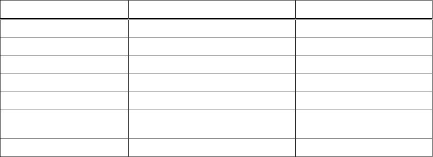
Table 4-1. Required Test Equipment
Equipment Type Required Specifications Recommended Type
DC and AC Voltage Calibrator 0 to 20 V dc ±0.002 % Fluke Model 5700A
Digital Multimeter 0 to 20 V dc ±0.002 %, Resolution: 1 µV HP3458A
Precision Shunt 0.01 Ω ±0.01 % dc, 0.035 % ac to 5 kHz Fluke Model Y5020
Load Resistor 0.01 Ω ±3 %, 50 W Dale RH-50
Load Resistor 0.01 Ω ±5 %, 10 W Dale RH-10
Distortion Analyzer Frequency range: 100 Hz to 5 kHz Sound Technology Model
1700A
Autotransformer Nominal line voltage ±10 %, 500 W General Radio Variac