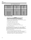
5 220A
Instruction Manual
4-22
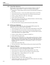
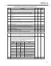
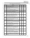
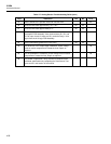
Table 4-6. Mainframe and Digital Section Troubleshooting Guide (cont.)
Step Instruction Yes No Go to
15 Check the line voltage switch settings on A2 Transformer
Assembly. They should be set to comply with the local line
voltage. If some voltages are in limits and some are out, the
problem is on the A4 Regulator or the A3 Cap Bus. If a voltage is
low, check for power supply loading. If a voltage is high, the
regulator IC is likely the cause.
Front Panel Tests
16 Complete the Front Panel Tests described earlier under
Performance Test.
17
17 Does the 5220A respond as described in the Front Panel Tests?
18 Do one or more LEDs light? 20 19
19 Operating voltage (+5 V dc) is not present at either the A9 Front
Panel PCB or the A10 Logic PCB. Repair as required.
20 Can the standby/operate modes be selected?
Note
The jumper wire must be installed between the
enabled output terminals.
21 Is the OVERCURRENT or OVERCOMPLIANCE LED lit? 23 22
22 Defective switch, LED, or standby/operate circuit (on the A10
Logic PCB).
16
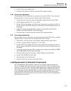
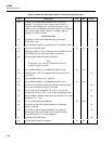
23 Set the POWER switch to OFF, then ON.
24 Is the OVERCURRENT or OVERCOMPLIANCE LED lit? 34 25
25 Connect a 0.1 Ω resistor between the selected output terminals,
then connect a DVM across the 0.1 Ω resistor.
26
26 Connect a jumper wire between TP4 (Turn on 1) on the A8
Analog Control PCB and TP7 (-15 V) on the A4 Regulator PCB.
27
27 With the 5220A in standby, adjust R6 on the A6 Driver for a DVM
reading of 0 V ±1.0 mV.
28
28 Can a 0 V DVM reading be obtained? 30 29
29 The A6 Driver and/or A7 Output Assemblies are defective.
Repair as required.
16
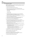
30 The A6 Driver and A7 Output Assemblies are functional.
Remove the jumper from between TP4 and the A8 Analog
Control PCB and TP17 on the A4 Regulator.
31
31 Press the STBY/OPR switch. 32
32 Can the operate mode be selected? 33 34


