Theory of Operation
Circuit Analysis
3
3-11
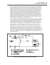
it were a logic level. That is, voltages from 0 to an approximate 2 V threshold are
considered a low logic level. A high logic level is approximately 2 to 4.5 V.
The TTL-to-FET level shifters are used to interface turn on/off commands TTL logic
levels, T1 and T2, from the A10 Logic with the standby/operate control FETs in the
transconductance amplifier. Both level shifters are identical in design. The input is
designed to respond to voltage levels from +0.01 to +5.0 V dc. Corresponding output
levels to drive the FET gates are 0 to –15 V dc.
3-12. A9 Front Panel
The A9 Front Panel Assembly contains the switches (with the exception of the power
switch) and LEDs that comprise the 5220A controls and indicators. The switches are used
to manually convey control information to the A10 Logic. This includes selection of the
local operating mode, standby/operate, and front/rear panel input. The LEDs display the
current operating status of the 5220A as determined by the A10 Logic. Status conditions
include: remote, local lockout (LLO), overcompliance, overcurrent, thermal cutout, front
panel input, rear panel input, standby, and operate.
Electrically, the LEDs (anode end) and the switches (arm) are connected to a common +5
V bus powered by the logic supply. A switch depression represents a +5 V output to the
A10 Logic. A series resistor connected to the anode end of each LED serves as a current
limiter when the LED is lit. A low logic level from the A10 Logic lights the appropriate
LEDs.
3-13. A10 Logic
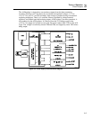
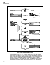
The A10 Logic, as shown in Figure 3-8, is designed to process and control the timing and
the input/output of all 5220A digital control data. Input data is received from the front
panel controls, the A11 MIS Bus Interface, and the analog protection circuits of the
transconductance amplifier. Output data provides timing and control signals to the
amplifier (including its relays) and the front panel indicator LEDs.
3-14. Reset Logic
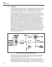
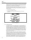
The reset logic consists of dual multivibrator U11, RC network R7/C2, or gate U9-10,
and inverter U3-10. Its function is to command the reset of the A10 Logic, and thus the
5220A, to an initial state when any one of the following events occur:
1. The 5220A is initially energized.
2. The +15/-15 V dc power supply is interrupted.
3. Control is switched from remote to local.
When the 5220A is energized the +5 V dc power supply rapidly rises to its +5 V level to
supply operating voltage to the A10 Logic Assembly. The voltage rise is integrated by
RC network R7, C2. The slow rising voltage across C2 is used as a momentary low logic
level to issue a reset command to all sections of the A10 Logic. Some sections are reset
directly by the voltage across C2 while others are reset indirectly by the response of U11-
10 to the voltage across C2.


