5 220A
Instruction Manual
3-16
3-19. Failure Status Logic
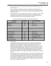
The failure status logic consists of three D-type flip-flop (U16-1, U16-13, and U17-13)
and their associated logic gates and drivers. Its function is to store failure conditions
detected by other parts of the A10 Logic and to drive the front panel STATUS indicators.
An optical isolator is also included for providing an Interface Overload Status signal to
the A11 MIS Bus Interface. Front panel status indicators comprise three LEDs:
OVERCOMPLIANCE, OVERCURRENT, and THERMAL CUTOUT. When any one of
these LEDs is lit, Interface Overload Status is driven high.
The inputs to the D-type flip-flop are connected to respond to three commands: reset,
clock, and set. The reset and clock inputs are used to set the Q outputs low, and thereby
remove the drive from the front panel STATUS LEDs. The three reset inputs are
connected in parallel and are commanded when the 5220A is initially energized and
when it is remotely commanded from standby to operate. The clock inputs are also
connected in parallel. They respond to a high input that transfers the low D-input to the Q
output. The clock is driven high under the following conditions:
1. When the STDBY/OPR pushbutton is pressed.
2. When the FRONT/REAR pushbutton is pressed.
3. When an onboard reset is initiated.
The set-inputs to the flip-flops in the failure status logic are used to set the Q outputs high
when a failure status is detected. This causes the corresponding STATUS LED to be lit
and the Interface Overload Status signal to go high. Each flip-flop responds to one of the
failure signals issued by the transconductance amplifier. They are:
1. Thermal Sw(itch) 1
2. Overcompliance
3. Overcurrent
3-20. A11 MIS Bus Interface
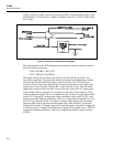
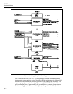
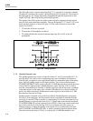
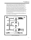
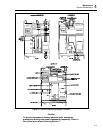
The A11 MIS Bus Interface, as shown in Figure 3-10, is a remote control interface that
allows the 5220A to operate as an extension of a 5100 Series Calibrator equipped with a
Model Y5000 Interface. An accessory cable is available for use with the Y5000 to
complete the necessary connections between the Y5000 and the A11 MIS Bus Interface.
Functionally, the A11 MIS Bus Interface (hereafter referred to as the MIS I/F) performs
three basic functions: receives and stores digital control data from a remote control
source (Y5000), interfaces 5220A status signals to the Y5000, and provides a connecting
path between the remote analog input signal (Aux Out) and the rear-input connections on
the A5 Preamplifier. Operating power for the assembly is derived from the +5 V ISO
(isolated) power supply.
Control data is received at the MIS I/F via the data bus as a 4-bit parallel word. When the
5100 Series Calibrator places the correct address on the address bus (BC0, BC3, and BC6
high), the write data logic responds by pulling the not ACK (acknowledge) line low and
clocking the control data word into the data register, U1. The not ACK signal is sent to
the 5100 to acknowledge the receipt of a valid address. The register outputs are buffered
and inverted by U6 before being used as remote programming inputs to the A10 Logic
PCB (i.e., not Remote, not Operate, not LLO and not Rear). At the same time that the
address is acknowledged, an RS flip-flop in the write data logic is set.
The function of the RS flip-flop is to prevent two successive status read inputs to the
5220A. The flip-flop is set when a high is present on inputs BC0, BC3, and BC6. This
results in a low output from U5-8 and a high output from U4-6. In this state gate U5-8 is


