Maintenance
General Maintenance
4
4-5
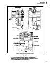
4-11. A6 Driver and A7 Output Assembly Removal
The A6 Driver and A7 Output PCB Assemblies comprise a plug-in assembly referred to
in this procedure as the A6 Driver/A7 Output. Use the following procedure to remove the
A6 Driver/A7 Output:
1. Remove the top cover from the 5220A.
2. Remove the large inner cover.
3. Remove the four screws from the sheet-metal portion of the A7 Output Assembly.
4. Remove the lug nuts holding the +12 and –12 V bus straps to the A3 Cap Bus.
5. Remove the front/rear output selection screws (jumpers).
6. Lift the A6 Driver/A7 Output from the chassis.
4-12. A3 Cap Bus Removal
To remove the A3 Cap Bus from the 5220A use the following procedure:
1. Remove the top and bottom covers from the 5220A.
2. Remove the top inner cover.
3. Remove both the front panel and the A9 Front Panel PCB Assembly.
4. Remove the A6 Driver/A7 Output Assembly.
5. Disconnect the transformer leads at the A3 Cap Bus.
6. Remove the two screws that secure the A3 Cap Bus ground strap to the motherboard.
7. Remove the nine screws holding the A3 Cap Bus to the front panel bulkhead.
8. On the A3 Cap Bus locate and the remove the two large-head screws located to the
side of resistors R2 and R5.
Caution
When these screws are installed they should be snug with the
PCB. However, they should not cause the PCB to bow.
9. Lift the A3 Cap Bus from the chassis.
Note
A heat-sink compound has been applied to the diode-end of the A3 Cap Bus.
Do not wipe off or otherwise remove this compound.
4-13. A12 Shunt Assembly Removal
Use the following procedure to remove the A12 Shunt Assembly:
1. Remove the top cover from the 5220A.
2. Remove both the large and small inner covers.
3. Remove the A8 Analog Control PCB Assembly from its connectors (J40).
4. Unplug the red-/black-lead connector next to J50 on the motherboard.
5. Locate the A12 Shunt Assembly (just in front of the fan) and remove the two screws
at the base of the assembly).
6. Carefully pull the A12 Shunt Assembly straight up while feeding the red-/black-leads
under the bulkhead. When the leads are free, remove the A12 Shunt Assembly from
the chassis.
Note
When reinstalling the shunt make sure that the red-/black-leads are plugged
into the motherboard; red lead to pin R, black lead to pin B.


