


3 - 11
3. SIGNALS AND WIRING
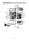
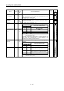
3.3 I/O signals
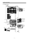
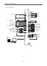
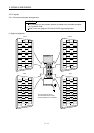
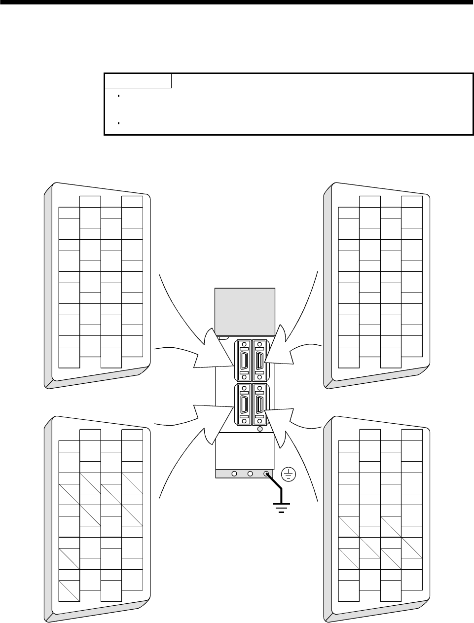
3.3.1 Connectors and signal arrangements
POINT
The connector pin-outs shown above are viewed from the cable connector
wiring section side.
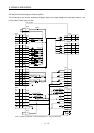
Refer to the next page for CN1A and CN1B signal assignment.
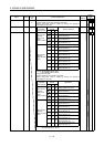
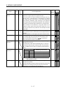
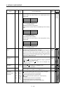
(1) Signal arrangement
1
2
3
5
4
6
7
9
8
10
11
12
13
14
15
16
17
18
19
20
RXD
MO1
TRE
LG
LG
RDP
SDP
TXD
MO2
P5
LG
LG
RDN
SDN
1
2
3
5
4
6
7
9
8
10
11
12
13
14
15
16
17
18
19
20
1
2
3
5
4
6
7
9
8
10
11
12
13
14
15
16
17
18
19
20
1
2
3
5
4
6
7
9
8
10
11
12
13
14
15
16
17
18
19
20
MD
LG
MDR
P5
LG
MRR
P5
LG
P5
BAT
MR
LG
MITSUBISHI
MELSERVO-J2
CN2 CN3
CN1A CN1B
The connector frames are
connected with the PE (earth)
terminal inside the servo amplifier.