


3 - 19
3. SIGNALS AND WIRING
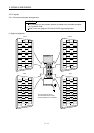
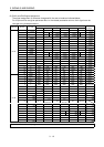
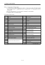
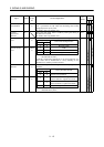
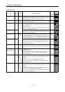
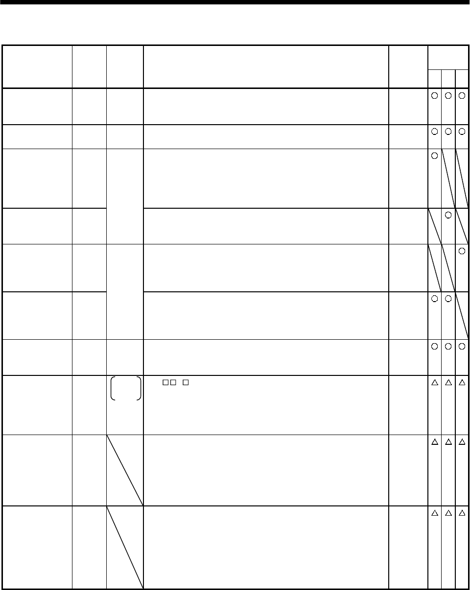
(2) Output signals
Control
mode
Signal Symbol
Connec-
tor pin
No.
Functions/Applications
I/O
division
PST
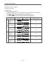
Trouble ALM CN1B
18
ALM-SG are disconnected when power is switched off or the
protective circuit is activated to shut off the base circuit. Without
alarm, ALM-SG are connected within 1 after power on.
DO-1
Ready RD CN1A
19
RD-SG are connected when the servo is switched on and the servo
amplifier is ready to operate.
DO-1
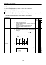
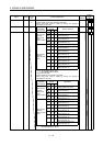
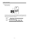
In position INP INP-SG are connected when the number of droop pulses is in the
preset in-position range. The in-position range can be changed
using parameter No. 5.
When the in-position range is increased, INP-SG may be kept
connected during low-speed rotation.
DO-1
Speed reached SA
CN1A
18
SA-SG are connected when the servo motor speed has nearly
reached the preset speed. When the preset speed is 50r/min or
less, SA-SG are kept connected.
DO-1
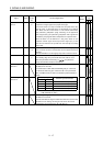
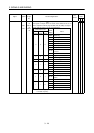
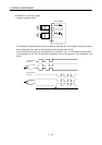
Limiting speed VLC VLC-SG are connected when speed reaches the value set to any of
the internal speed limits 1 to 7 (parameters No. 8 to 10, 72 to 75)
or the analog speed limit (VLA) in the torque control mode. They
are disconnected when the servo-on signal (SON) switches off.
DO-1
Limiting torque TLC
CN1B
6
TLC-SG are connected when the torque generated reaches the
value set to the internal torque limit 1 (parameter No. 28) or
analog torque limit (TLA). They are disconnected when the servo-
on signal (SON) switches off.
DO-1
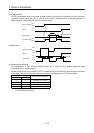
Zero speed ZSP CN1B
19
ZSP-SG are connected when the servo motor speed is zero speed
(50r/min) or less. Zero speed can be changed using parameter No.
24.
DO-1
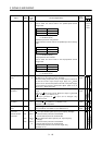
Electromagnetic
brake interlock
MBR CN1B
19
Set " 1 " in parameter No. 1 to use this parameter. Note that
ZSP will be unusable.
In the servo-off or alarm status, MBR-SG are disconnected.
When an alarm occurs, they are disconnected independently of
the base circuit status.
DO-1
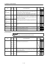
Warning WNG To use this signal, assign the connector pin for output using
parameter No.49. The old signal before assignment will be
unusable.
When warning has occurred, WNG-SG are connected.
When there is no warning, WNG-SG are disconnected within 1
second after power-on.
DO-1
Battery warning BWNG To use this signal, assign the connector pin for output using
parameter No.49. The old signal before assignment will be
unusable.
BWNG-SG are connected when battery cable breakage warning
(AL.92) or battery warning (AL.9F) has occurred.
When there is no battery warning, BWNG-SG are disconnected
within 1 second after power-on.
DO-1